background image

AUTOMIX screen

116


— Reference Guide

E

OVERWRITE

Switch recording on/off for each parameter. 
Each button corresponds to the following 
parameters.

FADER

Fader operations of each channel

CH ON

[ON] key operations of each channel

PAN

Pan operations of each channel

EQ

EQ operations of each channel

F

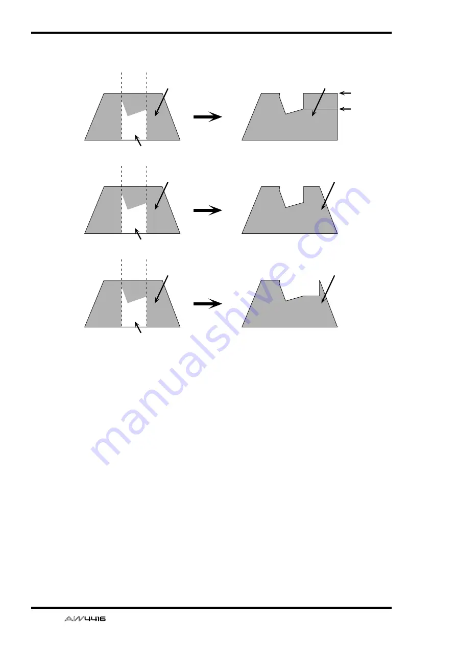
FADER EDIT MODE

Select one of the following two ways in which 
fader movements recorded in automix will be 
edited.

ABSOLUTE

This is the usual mode, in which previously-
recorded fader events are erased and the new 
events recorded.

RELATIVE

In this mode, the previously-recorded fader 
operation events are combined with the new 
events and recorded. This is convenient when 
you wish to add relative changes to the previ-
ously-recorded fader movements.

When END= on

Previously-recorded
fader movement

Fader movement
after editing

Edited fader movement

When RET= on,
END= off

Previously-recorded
fader movement

Fader movement
after editing

Edited fader movement

When RET= off,
END= off

Previously-recorded
fader movement

Fader movement
after editing

Edited fader movement

RET= on

RET= off

Summary of Contents for AW4416

Page 1: ...PROFESSIONAL AUDIO WORKSTATION E Reference Guide...

Page 2: ...7 QUICK REC screen 8 Quick Rec page 8 Simultaneously recording 16 inputs 16 tracks 8 MASTERING screen 10 Write CD page 10 Using a CD RW drive to create an audio CD 10 CD PLAY screen 12 CD Play page 1...

Page 3: ...35 Make overall settings for the AW4416 2 35 Prefer 3 page 37 Make overall settings for the AW4416 3 37 MIDI screen 39 MIDI Setup page 39 Make basic MIDI settings 39 MIDI Sync page 41 Make settings re...

Page 4: ...ng dynamics processor settings 62 Dly 1 16 Dly 17 24 Dly MONI pages 65 Set delay and phase 65 AUX1 AUX6 screens 67 Pre Pst IN Pre Pst MONI pages 67 Make on off and pre post settings for the AUX sends...

Page 5: ...een 90 TR View page 90 Viewing the recorded content for each track 90 V Track page 94 Switching virtual tracks 94 Stereo page 95 Playing or erasing the stereo track 95 Mark Adj page 97 Adjust or erase...

Page 6: ...Store or recall a scene 124 Fade Time page 126 Specify the fade time 126 RCL Safe page 127 Make fader recall safe settings 127 Sort page 128 Sort scenes 128 Appendix 1 Preset EQ Program Parameters 2 P...

Page 7: ...key to switch this button on off regardless of the cursor loca tion the EQ type to H SHELF shelving and turning it all the way in the counter clockwise direction will switch the EQ type to LPF low pa...

Page 8: ...frequency of the song PRT Song protect on off P 2 Tip If song protect is on the PRT column will show B SELECTED SONG NAME This shows the name of the song selected by the cursor This field is for displ...

Page 9: ...onds TIME CODE button The counter will be displayed as time code hours minutes seconds frames sub frames MEASURE button The counter will be displayed as measures measures beats ticks Tip The display m...

Page 10: ...rt point and end point refer to the explanation in TRACK screen Mark Adj page I RGN FADE TIME region fade time This parameter automatically fades in fades out the starting and ending point of regions...

Page 11: ...ng on the operation you may be able to select more than one song for edit ing B DELETE button This button deletes the song marked by the E symbol from the internal hard disk The current song cannot be...

Page 12: ...sor to this area and rotate the DATA JOG dial to specify the time signature 2 1 8 8 for that measure The numerator and denominator of the time signature can be set independently Tip When the AW4416 is...

Page 13: ...er that is currently input Tip For details on inputting the tempo map refer to Operation Guide Chapter 15 MIDI A maximum of 26 time signature data tempo data items can be input in the METER area TEMPO...

Page 14: ...n here in the song list is the data for when the song was last saved When you perform the Save pro cedure and press the ENTER key it will be overwritten by the new data B EXECUTE button In this page t...

Page 15: ...acks 1 8 SLOT1 1 8 INPUT 1 8 of an I O card slot 1 SLOT2 1 8 INPUT 1 8 of an I O card slot 2 Tip It is possible to select the same source for 1 and 2 In this case the same signal will be sent to track...

Page 16: ...ings for tracks 1 16 press the ALL SAFE key For details on operation of the Quick Rec function refer to Operation Guide Chapter 8 Patching Input channels 1 8 Input channels 9 16 Mixer section Input pa...

Page 17: ...writ ten using Track At Once to be playable on a CD player Tip If you used Disc At Once to write the data finalize will be performed automatically For this reason the FINALIZE button will be dis playe...

Page 18: ...om the track list K COPYRIGHT button Set the copy protect setting of the audio track currently selected in the track list Move the cursor to this button and press the ENTER key to switch between the f...

Page 19: ...io signal is routed through the stereo output channel and output from the STEREO OUT jacks Use the STEREO fader to adjust the volume During this time the signals of other channels will not be sent to...

Page 20: ...ditional functions in the CD Play page In the CD Play page you can press the SHIFT key to assign the following functions to the F1 F2 keys F1 CD LOAD key Close the tray of the CD RW drive F2 CD UNLOAD...

Page 21: ...nput channels 1 24 and return channels 1 2 The fol lowing signals can be assigned to each channel Input channels 1 24 Return channels 1 2 B EFFECT PATCH Select whether effects 1 2 will be used via AUX...

Page 22: ...inputs 1 16 Tip For detai ls on operations in the Patch IN page refer to Operation Guide Chapter 8 Patching Additional functions in the Patch IN page In the Patch IN page you can press the SHIFT key t...

Page 23: ...tab Screen functions A OMNI OUT ASSIGN Select the signals that will be output from the OMNI OUT 1 4 jacks The following signals can be assigned B D ST OUT ASSIGN digital stereo out assign C ST OUT AS...

Page 24: ...refer to Operation Guide Chapter 8 Patching Additional functions in the Patch OUT page In the Patch OUT page you can press the SHIFT key to assign the following function to the F1 key F1 CHANGE TAB k...

Page 25: ...e displayed as white characters on black background D TRACK 1 8 9 16 This area displays symbols to indicate the track inputs to which buses 1 8 and the direct output of the input channel currently sel...

Page 26: ...selected patching settings from the list This is the same function as the 7 RECALL button F4 STORE key Store the current patching settings This is the same function as the 8 STORE button To store the...

Page 27: ...ct one of the following clock source to which the AW4416 will synchronize SLOT 1 1 2 7 8 SLOT 2 1 2 7 8 The input signal from a digital I O card installed in OPTION I O slots 1 2 will be the clock sou...

Page 28: ...ial to make fine adjustments to the sam pling frequency over a range of 5 97 6 00 E STEREO BUS CASCADE This selects whether the digital device con nected to the DIGITAL STEREO IN jack will be cascaded...

Page 29: ...key press the SHIFT key F1 CHANGE TAB key to switch the tabs Mouse operation M button SETU button Monitor tab Screen functions A CHANNEL STATUS MONITOR This area monitors the state of the digital inp...

Page 30: ...the OPTION INPUTS area Additional functions in the Moni tor page In the Monitor page you can press the SHIFT key to assign the following function to the F1 key F1 CHANGE TAB key Switch between the two...

Page 31: ...I O slots OPTION OUT SLOT Tip Dithering is a process by which a small amount of noise is added to the signal in order to make the sound smoother prevent ing the obtrusive sound that can occur if bits...

Page 32: ...tab Screen functions A REC TRACK In pairs of adjacent odd numbered even numbered tracks tracks 1 2 3 4 this indi cates the tracks for which you can specify dith ering and word length The settings for...

Page 33: ...bus or to buses 1 8 or channels whose ON key is off MIXDOWN SOLO If this button is on the solo signal will be output via the stereo bus to the MONITOR OUT jacks PHONES jack When the Solo function is t...

Page 34: ...is sent to the SOLO bus when RECORDING SOLO mode is selected for 1 E SOLO SAFE CHANNEL This area selects the channels that will be excluded from the Solo function when MIX DOWN SOLO is selected for 1...

Page 35: ...was last saved SIZE Data size of the song BIT FS Quantization word length sampling frequency of the song PRT Song protect on off setting B BACKUP SONG button This button selects whether the song curre...

Page 36: ...ts of individual songs on one volume of media The selection of either TYPE 1 or TYPE 2 is made in the UTILITY screen Prefer 3 page P 37 For details on the song backup procedure refer to Operation Guid...

Page 37: ...NTER key to switch between ENABLE and DISABLE C ALL ENABLE button If you move the cursor to this button and press the ENTER key all songs will be selected for restore D ALL DISABLE button If you move...

Page 38: ...ype of drive that you select here If the internal hard disk or an external SCSI device MO or external hard disk is selected B EXECUTE button Execute formatting of the selected drive media Tip If a rem...

Page 39: ...orted by your CD RW drive E CD RW MEDIA ERASE Use the following two buttons to specify how the CD RW media will be erased SIMPLE Only the TOC Table Of Con tents of the CD RW media will be erased PERFE...

Page 40: ...tor on off Default OFF Sine waves and white noise have a higher sound pressure level than they appear to your ears Use caution since they may damage your speakers if played back at a high vol ume C LE...

Page 41: ...settings will appear in the upper right of the display when you operate the EQ PAN controls C STORE CONFIRMATION D RECALL CONFIRMATION If the 3 or 4 buttons are ON a popup window will ask you to conf...

Page 42: ...conds of the ROLL BACK key For details on rollback refer to Operation Guide Chapter 6 Transport locate operations Default 5 seconds C PREROLL POSTROLL TIME Specify the pre roll time 0 5 seconds and po...

Page 43: ...via a CD RW drive or the DIGITAL STEREO IN jack will be allowed ENABLE or not DISABLE When you move the cursor to the DISABLE button and press the ENTER key the following two page warning will be disp...

Page 44: ...to specify the movement speed of the mouse pointer Higher value will produce faster movement C INT SCSI TERMINATOR internal SCSI terminator This switches the internal SCSI bus terminator on off For d...

Page 45: ...his button is on a test will be performed before writing data to the CD R RW media to see whether writing errors will occur Default off WRITE button This turns data writing on off If the TEST button o...

Page 46: ...at program num ber C PROGRAM CHANGE OMNI If this button is on program changes of all MIDI channels will be received regardless of the Rx receive channel setting D PROGRAM CHANGE ECHO If this button is...

Page 47: ...able with Macintosh computers that have a modem printer port On the software that you use set the clock to 1 MHz Setting Computer platform Port type Transmission speed MIDI MIDI compatible MIDI IN OUT...

Page 48: ...age P 39 B MTC SYNC Specify whether the AW4416 will be the MTC master MASTER or slave SLAVE when MTC is used to synchronize an AW4416 song with the operation of an external MIDI device If master is se...

Page 49: ...ime code MTC received from the external device You can specify a range of 24 00 00 00 00 24 00 00 00 00 Tip The offset value you specify here does not affect the MTC that is transmitted from the MTC O...

Page 50: ...G dial to select the program number B SCENE MEM No scene memory num ber This is the scene number assigned to each pro gram number Move the cursor to this area and rotate the DATA JOG dial to select th...

Page 51: ...the attenuation value B PHASE Switch between normal N and reverse R phase C EQ equalizer Turn the EQ on off This area also displays a graph showing the approximate response of the current EQ settings...

Page 52: ...ir ing can also be set defeated in this page L ASSIGN button Use this button to insert an exter nal effect or internal effect into the channel Move the cursor to this button and press the ENTER key to...

Page 53: ...not be changed For the procedure of inserting an external effect into a channel refer to Operation Guide Chapter 8 Patching For the procedure of inserting an internal effect into a channel refer to Op...

Page 54: ...ng text refer to page 60 of the Operation Guide Library numbers 0 and 1 are recall only pre set programs and their names cannot be edited Also numbers in which channel set tings have not been stored w...

Page 55: ...the library title For details on inputting characters refer to Operation Guide page 60 5 Move the cursor to the OK button and press the ENTER key The settings will be stored When you execute the Store...

Page 56: ...return channels and monitor channels and set the bal ance of the stereo output channel Key operation PAN key F1 key Pan 1 16 F2 key Pan 17 24 F3 key Pan MONI Repeatedly press the PAN key until one of...

Page 57: ...ton The pan of paired channels will be linked while preserving the existing spatial relationship INVERTED GANG button The pan of paired channels will be linked inversely On the AW4416 the pan of a cha...

Page 58: ...ls This is the same function as the INVERTED GANG but ton F4 ALL ROUT OFF key Turn off bus assign 1 8 buttons for all channels in the page F5 COPY PAN TO ALL key Copy the pan setting of the currently...

Page 59: ...art symbol will be connected for chan nels buses that are paired and the button will be displayed as STEREO The heart symbol will be divided for channels buses that are not paired and the button will...

Page 60: ...PUT x y x odd number y even num ber The parameters of the odd numbered channel bus except for phase and pan will be copied to the even numbered channel INPUT y x x odd number y even num ber The parame...

Page 61: ...ob all the way in the clockwise direction will switch the EQ type to L SHELF shelving and turning it all the way in the counter clockwise direction will switch the EQ type to HPF high pass filter For...

Page 62: ...reo output channel is excepted Copying the attenuation setting to all channels Procedure 1 Access the EQ Att page for the copy source channel and move the cursor to the ATT knob 2 Press the SHIFT key...

Page 63: ...de P 60 Library numbers 1 40 are recall only preset memories and their names cannot be changed Numbers in which no EQ program has been stored are displayed as No Data and their title cannot be changed...

Page 64: ...nput the library title as desired For details on inputting characters refer to Opera tion Guide P 60 5 Move the cursor to the OK button and press the ENTER key The EQ settings will be stored Tip It is...

Page 65: ...he SEL key to select a channel that channel will be assigned to the corresponding fader group When you press the SEL key once again the channel will be removed from the fader group A channel cannot be...

Page 66: ...p When you press the SEL key once again the channel will be removed from the mute group Tip A mute group may contain both channels that are On and channels that are Off If a mute group contains channe...

Page 67: ...PRE EQ The pre EQ signal of the next channel to the left LEFT POST EQ or LEFT PRE EQ cannot be selected for input channel 1 monitor chan nel 1 or the stereo output channel Return channels 1 2 do not h...

Page 68: ...is shows the output level of the dynamics processor in dB units H CURVE This graph shows the approximate response of the current dynamics processor settings I TYPE This shows the type of the currently...

Page 69: ...put level of the dynamics processor in dB units E TITLE EDIT button Use this when you wish to edit the name library title of the dynamics program saved in the library Move the cursor to the TITLE EDIT...

Page 70: ...perations will apply to the pro gram enclosed by a dotted line in the library list In this page you can always use the DATA JOG dial to select the program regardless of where the cursor is located L C...

Page 71: ...and turn STORE CONFIRMA TION off 4 Input the library title For details on input ting characters refer to Operation Guide P 60 The Store operation will be executed Recalling dynamics settings from the...

Page 72: ...y MONI tab Screen functions A Channel This displays the channels for which you can make delay and phase set tings B DELAY Set the delay time for the signal of each channel The upper row shows the dela...

Page 73: ...py the delay time or phase setting selected by the cursor to all other channels Copying delay time or phase set tings to other channels 1 Access the DYN DLY screen Dly 1 16 Dly 17 24 Dly MONI page 2 M...

Page 74: ...t MONI tab Screen functions A Channels This area shows the channels whose AUX send pre post settings are being switched B ON OFF buttons These buttons are on off switches for the signal that is sent f...

Page 75: ...an press the SHIFT key to assign the following func tions to the F1 F2 keys F1 GLOBAL PRE key Switch all channels in that page to pre fader This is the same function as the PRE button in the GBL area...

Page 76: ...n or insertion is made in the SET UP screen Patch IN page B BYPASS ON OFF button This button switches effect bypass on off This ON OFF button can be switched by pressing the ENTER key regardless of wh...

Page 77: ...sound If the effect is patched via AUX send return set this to 100 If the effect is inserted in a specific channel adjust this to the desired value Tip This knob will be located in the same place reg...

Page 78: ...displayed as No Data and their name cannot be edited either E RECALL button Recall the currently selected effect program from the list If you select and attempt to recall a number in which nothing ha...

Page 79: ...and press the ENTER key The TITLE EDIT popup window will appear allowing you to assign a name to the effect pro gram 4 Input the library title as desired For details on inputting characters refer to...

Page 80: ...2 button Pre Pst IN tab Pre Pst MONI tab Screen functions A Channels This area shows the channels whose effect send pre post set tings are being switched B ON OFF buttons These buttons are on off swi...

Page 81: ...to the same effect creating a loop Additional functions in the Pre Pst IN Pre Pst MONI pages In the Pre Pst IN Pre Pst MONI pages you can press the SHIFT key to assign the following func tions to the...

Page 82: ...ts below each level meter B STEREO OUT LEVEL This shows the position of the STEREO fader in dB units C PRE EQ button D POST EQ button E POST FADER button Select one of these three buttons to select th...

Page 83: ...each chan nel is shown in dB units below each level meter B STEREO OUT LEVEL This shows the position of the STEREO fader in dB units C PRE EQ button D POST EQ button E POST FADER button Select one of...

Page 84: ...s 1 8 The fader location of each bus is shown in dB units below each fader Tip To adjust the value of a fader move the cur sor to the desired fader and rotate the DATA JOG dial C STEREO OUT LEVEL The...

Page 85: ...ed to OMNI OUT jacks 1 4 can be selected in the SETUP screen Patch OUT page B STEREO OUT level meter This meters shows the output level of stereo out put C STEREO OUT LEVEL This shows the position of...

Page 86: ...ted in slots 1 2 The type of signal assigned to each OUTPUT is indicated below each level meter Tip This page is for display only the assignments cannot be changed here The signals assigned to each OU...

Page 87: ...ove the cursor to this button and press the ENTER key the region you selected in 2 will be assigned to the pad you selected in 1 D T track This column shows the track number 1 16 E N name This column...

Page 88: ...unter at the top of the display to show the remaining time available for recording in the track F2 X ZOOM IN key Each time you press the SHIFT key F2 X ZOOM IN key the track view 7 will zoom in horizo...

Page 89: ...to select a track The value at the right shows the total time of that track D EXTRACT POINT Select the area of the track specified in 3 that will be assigned to the pad in units of min utes seconds f...

Page 90: ...ank will be selected e g A 1 A 2 B 1 B 2 and automati cally specified as a pair and the L R channels of the CD DA data will be assigned to these 5 Move the cursor to the TRACK TOTAL area and use the D...

Page 91: ...list of the WAV files on the internal CD RW drive or external SCSI device This list contains the following information FILE The file name directory name is displayed icons indicate WAV files and files...

Page 92: ...the list is selected for the operation Tip indicates the current directory and indicates the directory above To return to the next highest directory move the cursor to and press the ENTER key 5 Move...

Page 93: ...Select the bank pad number of the pad that you wish to name NAME Access the NAME EDIT screen where you can input a name You can input a maximum of 8 characters Tip Immediately after a sample has been...

Page 94: ...ease the available memory area E Pairing Here you can set or cancel pairing of adjacent odd numbered even numbered pads Move the cursor to the heart symbol and press the ENTER key to connect the heart...

Page 95: ...nning FR START and end FR END of the pad track selected in FR PAD that will be the copy source The specified portion of the performance will be the copy source pat tern TO PAD Specify the pad track to...

Page 96: ...NTER key the O display will change to and that pad track will no longer be played back If bank A B is selected by the BANK pad pads 1 8 of bank B A will be forcibly muted To cancel muting press the BA...

Page 97: ...han nels 1 16 C NAME This column shows the name of the virtual track currently selected for each track 1 16 When you record something on a track a default name of V Tr x y x track number 1 16 y virtua...

Page 98: ...s displayed at the bottom of the frame indicate locate points or markers that have been set in those locations The following types of symbols are displayed S Start point E End point I In point O Out p...

Page 99: ...ess the SHIFT key to assign the following additional functions to the F1 F4 keys F1 REMAIN key The remaining recordable time will be dis played in the level meter counter and in the dis play counter a...

Page 100: ...the DATA JOG dial toward the right will move the pointer forward and rotating it toward the left will move the pointer backward The keys of the locate transport section can not be used while the wavef...

Page 101: ...track numbers 1 16 C NAME This column shows the name of the virtual track that is currently selected for each track 1 16 D VIRTUAL TRACK Move the cursor to this column and press the ENTER key to selec...

Page 102: ...ng on the AW4416 B Track view Continuous audio data in the stereo track is dis played as a bar graph The symbols displayed below the track view indicate locate points and markers at those locations Th...

Page 103: ...for recording When you press the SHIFT key F1 REMAIN key once again the usual counter display will reappear Tip The remaining time available for recording will depend on the number of tracks that are...

Page 104: ...e If measure display is selected in the SONG screen Setting page only beats will be dis played for a location earlier than the start point IN OUT in point out point These locate points can be used as...

Page 105: ...refer to Opera tion Guide Chapter 6 Transport locate oper ations Be aware that locate points or markers you delete cannot be recovered Additional functions in the Mark Adj page In the Mark Adj page yo...

Page 106: ...dio data that was recorded in a single operation When you move the cursor to the desired menu and press the ENTER key a list of buttons will appear allowing you to select an editing com mand center co...

Page 107: ...set The symbols displayed at the bottom of the track view area indicate locate points and markers While editing the track and area selected for editing will be displayed as follows When selecting the...

Page 108: ...be copied YES or whether only the currently selected virtual track will be copied NO EXECUTE Execute the command Tip If you selected one track of a pair of tracks as the copy destination the same cont...

Page 109: ...l tracks as the subject of the operation To do so rotate the DATA JOG dial all the way clockwise when setting the TRACK parameter to make the selection read AL C ALL CUR RENT With this setting the STA...

Page 110: ...specified track At this time the move source audio data will be erased FR TRACK from track Select the move source track FR START from start Specify the starting location of the move source part FR END...

Page 111: ...be inserted END Specify the ending location of the part into which silence will be inserted ALL V TR all virtual tracks Select whether silence will be inserted into all virtual tracks included in the...

Page 112: ...their parameters are listed below NAME Modify the name of a region REGION Select the region whose name you wish to mod ify NAME Access the NAME EDIT popup window and input the new name Move the curso...

Page 113: ...units of a sample EXECUTE Execute the command T COMP time compression expansion Compress or expand the length of the selected region in a range of 50 200 without affect ing the pitch REGION Select the...

Page 114: ...V virtual track number This column shows the virtual track numbers 1 8 The virtual track currently used by the track 3 is indicated by a C Current symbol at the left of this column F NAME This column...

Page 115: ...the V TR Edit page In the V TR Edit page you can press the SHIFT key to assign the following additional functions to the F1 F3 keys F1 REMAIN key F2 X ZOOM IN key F3 X ZOOM OUT key These are the same...

Page 116: ...t which the imported CD DA data will be placed Tip The units used to specify this point will change depending on the counter display method time units measures selected in the SONG screen Setting page...

Page 117: ...and the disc will be inserted 3 Move the cursor to the DRIVE area use the DATA JOG dial to select the SCSI ID of the CD RW drive and press the ENTER key The AW4416 will detect the inserted CD and a s...

Page 118: ...screen Setting page If measure dis play is selected measures will be the smallest settable unit D TYPE Select whether the imported WAV file will be inserted into the track Insert or overwritten OverW...

Page 119: ...icates the current directory and indicates the directory above To return to the next highest directory move the cursor to and press the ENTER key 5 Move the cursor to the PASTE TO area and use the DAT...

Page 120: ...be displayed with the most recently saved content B SOURCE TRACK From the song selected in the song list 1 select the track number 1 16 and virtual track num ber 1 8 of the track that you wish to imp...

Page 121: ...firmation popup window will appear 7 Move the cursor to the OK button and press the ENTER key The track selected in the SOURCE TRACK field will be selected as the import source and the display will ch...

Page 122: ...e fader and other parameter values will change when automix recording ends END If this button is on all subsequent recorded events of the same parameter will be erased when you finish editing fader or...

Page 123: ...l mode in which previously recorded fader events are erased and the new events recorded RELATIVE In this mode the previously recorded fader operation events are combined with the new events and record...

Page 124: ...ry you can try using this button However the data prior to the most recent operation will be lost J AUTOMIX TRANSPORT These buttons control automix recording and playback By moving the cursor and pres...

Page 125: ...atically When automix is playing this button can be used in conjunction with the PLAY button to punch in AUTO REC button If you turn this button on lit and play back the recorder automix recording wil...

Page 126: ...l appear and recall will not be possible C STORE button This button stores the current automix data into memory You can select an automix number 1 16 as the store destination When you execute the Stor...

Page 127: ...he Memory page you can press the SHIFT key to assign the following functions to the F1 F3 keys F1 TITLE EDIT key Use this to edit the name memory title of auto mix data saved in memory This is the sam...

Page 128: ...e the fader to return it to the previous position B FADER EDIT OUT These are the same functions as the END RET buttons of the Main page Refer to the explana tion on page 115 If the RET button is on th...

Page 129: ...the ENTER key to select the type of events Each button corresponds to the following events SCENE LIB scene library button Scene memory and library recall events will be displayed The following types...

Page 130: ...will be re ordered automatically This means that the displayed order of the events may change E EVENT This area shows the type of each event Move the cursor here and rotate the DATA JOG dial to edit t...

Page 131: ...brary name of up to 16 characters For details on inputting characters refer to page 60 of the Operation Guide It is not possible to change the name of scene number 0 or of a scene in which PROTEC TION...

Page 132: ...all scene num bers 1 50 51 96 Additional functions in the Scene Mem page In the Scene Mem page you can press the SHIFT key to assign the following functions to the F1 F3 keys F1 TITLE EDIT key Use th...

Page 133: ...channel Fade time will have no effect unless it is spec ified for the scene being recalled even if it is specified for the current scene The fade time is specified independently for each scene Be sur...

Page 134: ...g channels can be set to Recall Safe sta tus Input channels 1 24 Monitor channels 1 16 Effect return channels 1 2 Stereo output channel Tip When a scene is recalled Fader Recall Safe is valid only if...

Page 135: ...or to this list and rotate the DATA JOG dial to select the scene whose sorting order you wish to change The currently selected scene will be highlighted B DESTINATION Specify the scene number to which...

Page 136: ...ors 24 Preset Dynamics Programs 24 Preset Dynamics Program Parameters 29 Troubleshooting 35 Display message list 39 Messages 39 Popup messages 41 Specifications 43 General Specifications 43 Mixer sect...

Page 137: ...ING Emphasizes the attack of tom toms and creates a long leathery decay Q 1 4 10 1 2 0 28 F 210Hz 667Hz 4 49kHz 6 35kHz G 2 0dB 7 5dB 2 0dB 1 0dB 006 Cymbal L SHELF PEAKING PEAKING H SHELF Emphasizes...

Page 138: ...0dB 5 5dB 0 5dB 2 5dB 016 E G Crunch 1 PEAKING PEAKING PEAKING PEAKING Adjusts the tonal quality of a slightly distorted guitar sound Q 8 4 5 0 63 9 F 140Hz 1 00kHz 1 88kHz 5 65kHz G 4 5dB 0 0dB 4 0d...

Page 139: ...1 PEAKING PEAKING PEAKING PEAKING Use as a template for female vocal Adjust the HIGH or H MID setting according to the voice quality Q 0 18 0 45 0 56 0 14 F 118Hz 397Hz 2 67kHz 5 99kHz G 1 0dB 1 0dB 1...

Page 140: ...0 0dB 036 Piano 3 PEAKING PEAKING PEAKING H SHELF This is a variation on program 013 Q 8 10 9 F 99Hz 472Hz 2 37kHz 10 0kHz G 4 5dB 13 0dB 4 5dB 2 5dB 037 Piano Low PEAKING PEAKING PEAKING H SHELF Use...

Page 141: ...t need to use complex parameter settings 09 Stereo Delay STEREO DELAY Stereo delay with independent left and right 10 Mod delay MOD DELAY Mono delay with modulation 11 Delay LCR DELAY LCR Three tap de...

Page 142: ...to MIDI Title Type Description 29 Rev Chorus REV CHORUS Reverb and chorus in parallel 30 Rev Chorus REV CHORUS Reverb and chorus in series 31 Rev Flange REV FLANGE Reverb and flanger in parallel 32 Re...

Page 143: ...LVL OFF 60 to 0 dB Level at which gate kicks in ATTACK 0 120 ms Gate opening speed HOLD 1 1 0 02 ms 2 13 s fs 44 1 kHz 0 02 ms 1 96 s fs 48 kHz Gate open time DECAY 2 2 6 0 ms 46 0 s fs 44 1 kHz 5 0 m...

Page 144: ...e effects and dry sounds Parameter Range Description DELAY 0 0 2730 0 ms Delay time FB GAIN 99 to 99 Feedback gain plus values for normal phase feedback minus values for reverse phase feedback HI RATI...

Page 145: ...e feedback minus values for reverse phase feedback HI RATIO 0 1 1 0 High frequency feedback ratio HPF Thru 21 Hz 8 0 kHz High pass filter cutoff frequency LPF 50 Hz 16 0 kHz Thru Low pass filter cutof...

Page 146: ...uency HSH G 12 to 12 dB High shelving filter gain MIX BAL 0 100 Mix balance of the effects and dry sounds Parameter Range Description FREQ 0 05 40 00 Hz Modulation speed DEPTH 0 100 Modulation depth M...

Page 147: ...lues for normal phase feedback minus values for reverse phase feedback OFFSET 0 100 Lowest phase shifted frequency offset STAGE 2 4 8 10 12 14 16 Number of phase shift stages LSH F 21 2 8 00 k Hz Low...

Page 148: ...r normal phase feedback minus values for reverse phase feedback MODE 1 10 Pitch shift precision MIX BAL 0 100 Mix balance of the effects and dry sounds Parameter Range Description PITCH 1 24 to 24 sem...

Page 149: ...3000 0 Hz Oscillator frequency FM FREQ 0 05 40 00 Hz Oscillator frequency modulation speed FM DEPTH 0 100 Oscillator frequency modulation depth MIX BAL 0 100 Mix balance of the effects and dry sounds...

Page 150: ...LE 0 100 Middle tone control TREBLE 0 100 High tone control EQ F 99 8 0 kHz Parametric equalizer frequency EQ G 12 to 12 dB Parametric equalizer gain EQ Q 10 0 0 10 Parametric equalizer bandwidth MIX...

Page 151: ...EQ Q 10 0 10 Parametric equalizer band width HSH F 50 0 16 0 k Hz High shelving filter frequency HSH G 12 to 12 dB High shelving filter gain MIX BAL 0 100 Mix balance of the effects and dry sounds Pa...

Page 152: ...ay time WAVE Sine Tri Modulation waveform REV CHO 0 100 Reverb and chorus balance 0 chorus 100 reverb MIX BAL 0 100 Mix balance of the effects and dry sounds Parameter Range Description REV TIME 0 3 9...

Page 153: ...feedback WAVE Sine Tri Modulation waveform REV FLG 0 100 Reverb and flange balance 0 flange 100 reverb MIX BAL 0 100 Mix balance of the effects and dry sounds Parameter Range Description REV TIME 0 3...

Page 154: ...y time WAVE Sine Tri Modulation waveform REV SYM 0 100 Reverb and symphonic balance 0 symphonic 100 reverb MIX BAL 0 100 Mix balance of the effects and dry sounds Parameter Range Description REV TIME...

Page 155: ...of the effects and dry sounds Parameter Range Description DELAY L 0 0 1000 0 ms Left channel delay time DELAY R 0 0 1000 0 ms Right channel delay time FB DLY 0 0 1000 0 ms Feedback delay time FB GAIN...

Page 156: ...F Thru 21 Hz 8 0 kHz High pass filter cutoff frequency LPF 50 Hz 16 0 kHz Thru Low pass filter cutoff frequency DLY ER 0 100 Delay and early reflected delay balance 0 early reflected delay 100 delay M...

Page 157: ...rb spreed DENSITY 0 100 Reverb density HPF Thru 21 Hz 8 0 kHz High pass filter cutoff frequency LPF 50 Hz 16 0 kHz Thru Low pass filter cutoff frequency DLY REV 0 100 Delay and delayed reverb balance...

Page 158: ...band pass TYPE 3 HPF LPF BPF Filter 3 type low pass high pass band pass FREQ 1 28 Hz 16 0 kHz Filter 1 frequency FREQ 2 28 Hz 16 0 kHz Filter 2 frequency FREQ 3 28 Hz 16 0 kHz Filter 3 frequency LEVE...

Page 159: ...namics programs No Program Name No Program Name 001 A Dr BD CMP 021 BrassSection CMP 002 A Dr BD EXP 022 Syn Pad CMP 003 A Dr BD GAT 023 SamplingPerc CPS 004 A Dr BD CPH 024 Sampling BD CMP 005 A Dr S...

Page 160: ...Out Gain sets the compressor s output signal level Compression tends to reduce the average signal level Out Gain can be used to counter this level reduction and set an appropriate level for the next...

Page 161: ...a slow attack time the initial transient of a sound passes through unaffected Out Gain sets the expander s output signal level Knee sets the transition of the signal at the threshold With a hard knee...

Page 162: ...ttack controls how soon the signal is companded once the compander has been triggered With a fast attack time the signal is companded almost immediately With a slow attack time the initial transient o...

Page 163: ...he signal to be virtually cutoff At a setting of 30 dB the signal is ducked by 30 dB At a setting of 0 dB the duck has no effect Attack determines how fast the gate opens when the signal exceeds the t...

Page 164: ...ram 001 Ratio 1 1 7 Attack ms 1 Outgain dB 3 5 Knee 2 Release ms 70 003 A Dr BD GAT Gate Threshold dB 11 Gate for the same purpose as program 001 Range dB 53 Attack ms 0 Hold ms 1 93 Decay ms 400 004...

Page 165: ...erentiate the bass and snare drums clearly Ratio 1 2 Attack ms 38 Outgain dB 3 5 Width dB 54 Release ms 842 011 E B finger CMP Compressor Threshold dB 12 Compressor to equalize the attack and volume l...

Page 166: ...1 5 Knee 2 Release ms 238 018 Strings1 CMP Compressor Threshold dB 11 Compressor for string instruments This program was intended for violins Ratio 1 2 Attack ms 33 Outgain dB 1 5 Knee 2 Release ms 74...

Page 167: ...ass drum sounds Ratio 1 2 Attack ms 2 Outgain dB 3 5 Knee 4 Release ms 35 025 Sampling SN CMP Compressor Threshold dB 18 A variation on program 023 intended for sampled snare drum sounds Ratio 1 4 Att...

Page 168: ...the musicians are using Ratio 1 2 Attack ms 1 Outgain dB 2 0 Knee 2 Release ms 284 033 Announcer CPH CompanderH Threshold dB 14 Hard compander reduces the level during the interval between the words...

Page 169: ...eo out during mixdown It is also interesting on stereo input signals Ratio 1 2 5 Attack ms 60 Outgain dB 0 0 Knee 2 Release ms 1 12 S 039 Total Comp2 CMP Compressor Threshold dB 18 A variation of prog...

Page 170: ...und is not output Has audio data been recorded on the recorder Muting may be enabled in the TRACK screen TR View page The input monitor mode may be set to INPUT Is the virtual track set to the track t...

Page 171: ...recording The AW4416 may be set to record the digital input signal Make sure that CD DAT DIGITAL REC is set to ENABLE Can t change input patches during recording The AW4416 may be set to record the di...

Page 172: ...tal input sounds grainy Is the dither setting appropriate Pairing was specified but the signal is monaural Is the odd numbered channel panned far left and the even numbered channel panned far right Pa...

Page 173: ...ot recognized Is the CD RW drive connected correctly Can t create an audio CD Is CD R media inserted The inserted CD R may have already been final ized Is a signal recorded on the stereo track The ste...

Page 174: ...word clock source CANNOT SELECT WC EXTERNAL Since the external word clock is selected as the word clock source the AW4416 cannot be set as the MTC slave CANNOT SET MARK It is not possible to specify...

Page 175: ...than one second SELECTED AREA HAS NO DATA The selected area contains no trigger data SELECTED AREA HAS NO REGION The selected area contains no region SELECTED CH IS NONE The selected channel cannot b...

Page 176: ...le Since the disk is full a CD image file cannot be created Can t Delete Current Song The currently loaded song cannot be deleted Can t Delete Protected Song A protected song cannot be deleted Can t E...

Page 177: ...cted drive contains no WAV files Not WAV File The file is not a WAV file Partition Not Found The specified partition was not found Recall Channel Data Conflict The specified channel library cannot be...

Page 178: ...els stereo 1 PHONES 2 channels stereo 1 DIGITAL STEREO OUT 2 channels stereo 1 mini YGDAI card option max 16 channels Mixing layer section 44 channels Input channel 24 channels Internal effect return...

Page 179: ...put output MIC LINE input Channel 1 2 balanced XLR type TRS phone jack 48 V DC phantom powering PEAK LED 3 dB clipping level Input impedance 3 k Nominal input level 46 dB to 4 dB Minimum input level 5...

Page 180: ...0 Maximum output level 100 mW 100 mW 40 load DIGITAL STEREO I O Coaxial phono Option card slot Slot 2 Digital I O MY 8 AT Adat MY 8 TD Tascam MY 8 AE AES EBU Analog input MY 8 AD TRS phone jack 8 MY 4...

Page 181: ...rding tracks Tracks 130 tracks 16 tracks 8 virtual tracks plus ste reo track Format File system AW4416 original format Internal hard disk drive 2 5 IDE Max hard disk capacity 64 GB 8 GB partition Max...

Page 182: ...TY MIDI MIXER buttons VIEW PAN EQ DYN FADER MODE buttons AUX1 AUX2 AUX3 AUX4 AUX5 AUX6 AUX7 AUX8 HOME MIXING LAYER buttons 1 16 17 24 RTN MONI ON buttons SEL buttons Faders 1 8 channel 1 8 channel 17...

Page 183: ...DO button REDO button CUR SOR button DATA ENTRY but ton JOG SHUTTLE ENTER button Display 320 240 dots graphical LCD with contrast control 3 color FL display Control I O WORD CLOCK IN BNC WORD CLOCK OU...

Page 184: ...cifications and external appearance subject to change without notice For European Model Purchaser User Information specified in EN55103 1 and EN55103 2 Inrush Current 30A Conformed Environment E1 E2 E...

Page 185: ...ntinue commands will be transmitted by the corresponding operations and MIDI Clock and Song Posi tion Pointer messages will be transmitted according to the MIDI Tempo Map 1 6 MTC master If you select...

Page 186: ...e below for details If velocity is 0x00 same as note off STATUS 1001nnnn 9n Note On Message DATA 0nnnnnnn nn Note No 0vvvvvvv vv Velocity 1 127 On 0 off Notes used to control effects 1 Dynamic Flange...

Page 187: ...ystem Exclu sive Device ID 0ddddddd dd Destination 00 7E 7F all call Command 00000110 06 Machine Control Command mcc sub id 00000001 01 Stop MCS EOX 11110111 F7 End Of Exclusive 4 13 2 MMC PLAY Recept...

Page 188: ...information field STATUS 11110000 F0 System Exclusive Message ID No 01111111 7F Real Time System Exclu sive Device ID 0ddddddd dd Destination 00 7E 7F all call Command 00000110 06 Machine Control Comm...

Page 189: ...X X After Touch Key s Ch s X X X X Pitch Bend X X Control Change X X Prog Change True 0 127 0 127 0 96 System Exclusive X O 1 System Common Song Pos Song Sel Tune O X X X X X 2 System Real Time Clock...

Page 190: ...TOR SLOT1 OUT SLOT2 OUT 2 2 8 8 16 46 16 L R LEVEL LEVEL LEVEL BAL ON INSERT METER METER METER METER METER METER METER METER METER METER METER X 2 X 4 0dB L R 4dB 8 8 DA RECORDER TRACK CUE Logic MIXER...

Page 191: ...YAMAHA CORPORATION V566460 R1 1 IP 194 Pro Audio Digital Musical Instrument Division P O Box 3 Hamamatsu 430 8651 Japan 00 09 7000 AP Printed in Japan...

Reviews: