


ELECTRICAL COMPONENTS
7-36
TIP
Voltage should be measured 30 minutes after
the machine is stopped.
b. Connect a charged and AMP meter to the
battery and start charging.
TIP
Set the charging voltage at 16–17 V.If the set-
ting is lower, charging will be insufficient. If too
high, the battery will be over-charged.
c. Make sure that the current is higher than
the standard charging current written on
the battery.
TIP
If the current is lower than the standard charg-
ing current written on the battery, set the
charging voltage adjust dial at 20–24 V and
monitor the amperage for 3–5 minutes to
check the battery.
d. Adjust the voltage so that the current is at
the standard charging level.
e. Set the time according to the charging time
suitable for the open-circuit voltage.
Refer to “Battery condition checking steps”.
f.
If charging requires more than 5 hours, it is
advisable to check the charging current
after a lapse of 5 hours. If there is any
change in the amperage, readjust the volt-
age to obtain the standard charging cur-
rent.
g. Measure the battery open-circuit voltage
after leaving the battery unused for more
than 30 minutes.
▲▲▲▲▲▲▲▲▲▲▲▲▲▲▲▲▲▲▲▲▲▲▲▲▲▲▲▲▲▲
▼▼▼▼▼▼▼▼▼▼▼▼▼▼▼▼▼▼▼▼▼▼▼▼▼▼▼▼▼▼
Charging method using a constant voltage
charger
a. Measure the open-circuit voltage prior to
charging.
TIP
Voltage should be measured 30 minutes after
the machine is stopped.
b. Connect a charger and AMP meter to the
battery and start charging.
c. Make sure that the current is higher than
the standard charging current written on
the battery.
TIP
If the current is lower than the standard charg-
ing current written on the battery, This type of
battery charger cannot charge the VRLA
(Valve Regulated Lead Acid) battery. A vari-
able voltage charger is recommended.
d. Charge the battery until the battery’s charg-
ing voltage is 15 V.
TIP
Set the charging time at 20 hours (maximum).
e. Measure the battery open-circuit voltage
after leaving the battery unused for more
than 30 minutes.
▲▲▲▲▲▲▲▲▲▲▲▲▲▲▲▲▲▲▲▲▲▲▲▲▲▲▲▲▲▲
6. Install:
• Battery
7. Connect:
• Battery leads
(to the battery terminals)
ECA13630
First, connect the positive battery lead “1”,
and then the negative battery lead “2”.
8. Check:
• Battery terminals
Dirt
→
Clean with a wire brush.
Loose connection
→
Connect properly.
• Reach the standard charging current
Battery is good.
• Does not reach the standard charging cur-
rent
Replace the battery.
12.8 V or more --- Charging is complete.
12.7 V or less --- Recharging is required.
Under 12.0 V --- Replace the battery.
12.8 V or more --- Charging is complete.
12.7 V or less --- Recharging is required.
Under 12.0 V --- Replace the battery.
Summary of Contents for 2009 YFM25RY
Page 1: ...SERVICE MANUAL YFM25RY YFM25RSEY YFM25RSE2Y 4D3 28197 11 LIT 11616 22 09 2009 ...
Page 8: ......
Page 39: ...LUBRICATION POINTS AND LUBRICANT TYPES 2 20 ...
Page 42: ...LUBRICATION SYSTEM CHART AND DIAGRAMS 2 23 EAS20410 LUBRICATION DIAGRAMS ...
Page 44: ...LUBRICATION SYSTEM CHART AND DIAGRAMS 2 25 ...
Page 46: ...LUBRICATION SYSTEM CHART AND DIAGRAMS 2 27 ...
Page 47: ...LUBRICATION SYSTEM CHART AND DIAGRAMS 2 28 1 Oil cooler 2 Oil hose 1 3 Oil hose 2 ...
Page 48: ...CABLE ROUTING 2 29 EAS20430 CABLE ROUTING ...
Page 50: ...CABLE ROUTING 2 31 ...
Page 52: ...CABLE ROUTING 2 33 ...
Page 54: ...CABLE ROUTING 2 35 ...
Page 56: ...CABLE ROUTING 2 37 ...
Page 58: ...CABLE ROUTING 2 39 ...
Page 60: ...CABLE ROUTING 2 41 ...
Page 62: ...CABLE ROUTING 2 43 ...
Page 65: ......
Page 143: ...HANDLEBAR 4 42 Throttle cable free play 2 0 4 0 mm 0 08 0 16 in ...
Page 162: ...CHAIN DRIVE 4 61 ...
Page 165: ......
Page 240: ...CARBURETOR 6 9 ...
Page 242: ...IGNITION SYSTEM 7 1 EAS27090 IGNITION SYSTEM EAS27100 CIRCUIT DIAGRAM ...
Page 246: ...ELECTRIC STARTING SYSTEM 7 5 EAS27160 ELECTRIC STARTING SYSTEM EAS27170 CIRCUIT DIAGRAM ...
Page 252: ...CHARGING SYSTEM 7 11 EAS27200 CHARGING SYSTEM EAS27210 CIRCUIT DIAGRAM ...
Page 255: ...CHARGING SYSTEM 7 14 ...
Page 256: ...LIGHTING SYSTEM 7 15 EAS27240 LIGHTING SYSTEM EAS27250 CIRCUIT DIAGRAM ...
Page 260: ...SIGNALING SYSTEM 7 19 EAS27270 SIGNALING SYSTEM EAS27280 CIRCUIT DIAGRAM ...
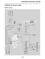
Page 264: ...CARBURETOR HEATING SYSTEM 7 23 EAS27490 CARBURETOR HEATING SYSTEM EAS27500 CIRCUIT DIAGRAM ...
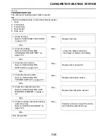
Page 267: ...CARBURETOR HEATING SYSTEM 7 26 ...
Page 268: ...ELECTRICAL COMPONENTS 7 27 EAS27972 ELECTRICAL COMPONENTS ...
Page 270: ...ELECTRICAL COMPONENTS 7 29 EAS27980 CHECKING THE SWITCHES ...
Page 284: ...ELECTRICAL COMPONENTS 7 43 ...
Page 291: ......
Page 292: ...YAMAHA MOTOR CO LTD 2500 SHINGAI IWATA SHIZUOKA JAPAN ...
Page 293: ...WIRING DIAGRAM YFM25RY YFM25RSEY YFM25RSE2Y ...