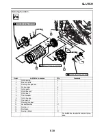


CYLINDER AND PISTON
5-28
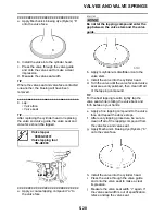
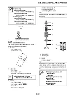
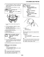
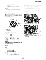
• Upper oil ring rail “3”
• 2nd ring “4”
• Top ring “5”
TIP
Be sure to install the piston rings so that the
“T” marks or numbers face up.
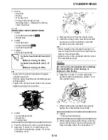
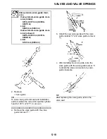
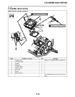
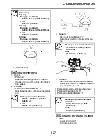
2. Install:
• Piston “1”
• Piston pin “2”
• Piston pin clips “3”
TIP
• Apply engine oil the piston pin.
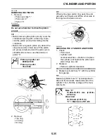
• Make sure the dot “a” on the piston points
towards the exhaust side of the cylinder.
• Before installing the piston pin clip, cover the
crankcase opening with a clean rag to pre-
vent the clip from falling into the crankcase.
3. Install:
• O-ring
• Cylinder gasket
• Dowel pins
4. Lubricate:
• Piston
• Piston rings
• Cylinder
(with the recommended lubricant)
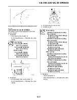
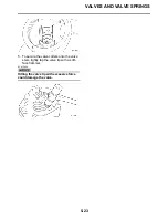
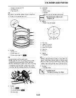
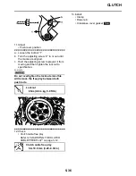
5. Offset:
• Piston ring end gaps
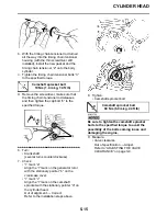
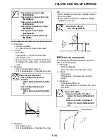
6. Install:
• Cylinder
TIP
• While compressing the piston rings with one
hand, install the cylinder with the other hand.
• Pass the timing chain and timing chain guide
(intake side) through the timing chain cavity.
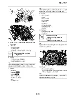
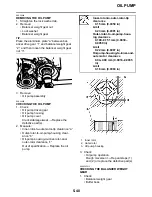
7. Tighten:
• Cylinder bolt
New
New
New
Recommended lubricant
Engine oil
a. Top ring
b. Upper oil ring rail
c. Oil ring expander
d. Lower oil ring rail
e. 2nd ring
f. 20 mm
Cylinder bolt
10 Nm (1.0 m·kg, 7.4 ft·lb)
Summary of Contents for 2009 YFM25RY
Page 1: ...SERVICE MANUAL YFM25RY YFM25RSEY YFM25RSE2Y 4D3 28197 11 LIT 11616 22 09 2009 ...
Page 8: ......
Page 39: ...LUBRICATION POINTS AND LUBRICANT TYPES 2 20 ...
Page 42: ...LUBRICATION SYSTEM CHART AND DIAGRAMS 2 23 EAS20410 LUBRICATION DIAGRAMS ...
Page 44: ...LUBRICATION SYSTEM CHART AND DIAGRAMS 2 25 ...
Page 46: ...LUBRICATION SYSTEM CHART AND DIAGRAMS 2 27 ...
Page 47: ...LUBRICATION SYSTEM CHART AND DIAGRAMS 2 28 1 Oil cooler 2 Oil hose 1 3 Oil hose 2 ...
Page 48: ...CABLE ROUTING 2 29 EAS20430 CABLE ROUTING ...
Page 50: ...CABLE ROUTING 2 31 ...
Page 52: ...CABLE ROUTING 2 33 ...
Page 54: ...CABLE ROUTING 2 35 ...
Page 56: ...CABLE ROUTING 2 37 ...
Page 58: ...CABLE ROUTING 2 39 ...
Page 60: ...CABLE ROUTING 2 41 ...
Page 62: ...CABLE ROUTING 2 43 ...
Page 65: ......
Page 143: ...HANDLEBAR 4 42 Throttle cable free play 2 0 4 0 mm 0 08 0 16 in ...
Page 162: ...CHAIN DRIVE 4 61 ...
Page 165: ......
Page 240: ...CARBURETOR 6 9 ...
Page 242: ...IGNITION SYSTEM 7 1 EAS27090 IGNITION SYSTEM EAS27100 CIRCUIT DIAGRAM ...
Page 246: ...ELECTRIC STARTING SYSTEM 7 5 EAS27160 ELECTRIC STARTING SYSTEM EAS27170 CIRCUIT DIAGRAM ...
Page 252: ...CHARGING SYSTEM 7 11 EAS27200 CHARGING SYSTEM EAS27210 CIRCUIT DIAGRAM ...
Page 255: ...CHARGING SYSTEM 7 14 ...
Page 256: ...LIGHTING SYSTEM 7 15 EAS27240 LIGHTING SYSTEM EAS27250 CIRCUIT DIAGRAM ...
Page 260: ...SIGNALING SYSTEM 7 19 EAS27270 SIGNALING SYSTEM EAS27280 CIRCUIT DIAGRAM ...
Page 264: ...CARBURETOR HEATING SYSTEM 7 23 EAS27490 CARBURETOR HEATING SYSTEM EAS27500 CIRCUIT DIAGRAM ...
Page 267: ...CARBURETOR HEATING SYSTEM 7 26 ...
Page 268: ...ELECTRICAL COMPONENTS 7 27 EAS27972 ELECTRICAL COMPONENTS ...
Page 270: ...ELECTRICAL COMPONENTS 7 29 EAS27980 CHECKING THE SWITCHES ...
Page 284: ...ELECTRICAL COMPONENTS 7 43 ...
Page 291: ......
Page 292: ...YAMAHA MOTOR CO LTD 2500 SHINGAI IWATA SHIZUOKA JAPAN ...
Page 293: ...WIRING DIAGRAM YFM25RY YFM25RSEY YFM25RSE2Y ...