
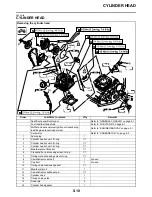
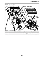
CYLINDER HEAD
5-13
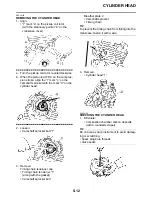
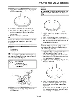
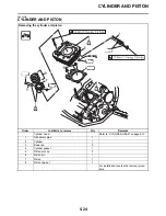
2. Check:
• Cylinder head
Damage/scratches
→
Replace.
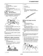
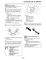
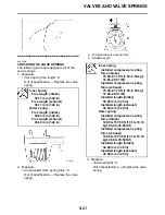
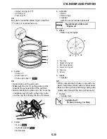
3. Measure:
• Cylinder head warpage
Out of specification
→
Resurface the cyl-
inder head.
▼▼▼▼▼▼▼▼▼▼▼▼▼▼▼▼▼▼▼▼▼▼▼▼▼▼▼▼▼▼
a. Place a straightedge “1” and a thickness
gauge “2” across the cylinder head.
b. Measure the warpage.
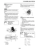
c. If the limit is exceeded, resurface the cylin-
der head as follows.
d. Place a 400–600 grit wet sandpaper on the
surface plate and resurface the cylinder
head using a figure-eight sanding pattern.
TIP
To ensure an even surface, rotate the cylinder
head several times.
▲▲▲▲▲▲▲▲▲▲▲▲▲▲▲▲▲▲▲▲▲▲▲▲▲▲▲▲▲▲
EAS24180
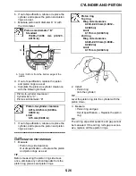
CHECKING THE TIMING CHAIN GUIDES
The following procedure applies to all of the
camshaft sprockets and timing chain guides.
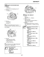
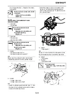
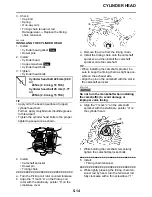
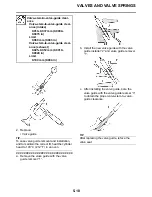
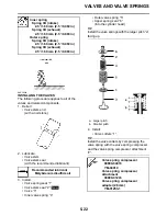
1. Check:
• Camshaft sprocket
More than 1/4 tooth wear “a”
→
Replace
the camshaft sprockets and the timing
chain as a set.
2. Check:
• Timing chain guide (exhaust side)
Damage/wear
→
Replace the defective
part(s).
EAS24200
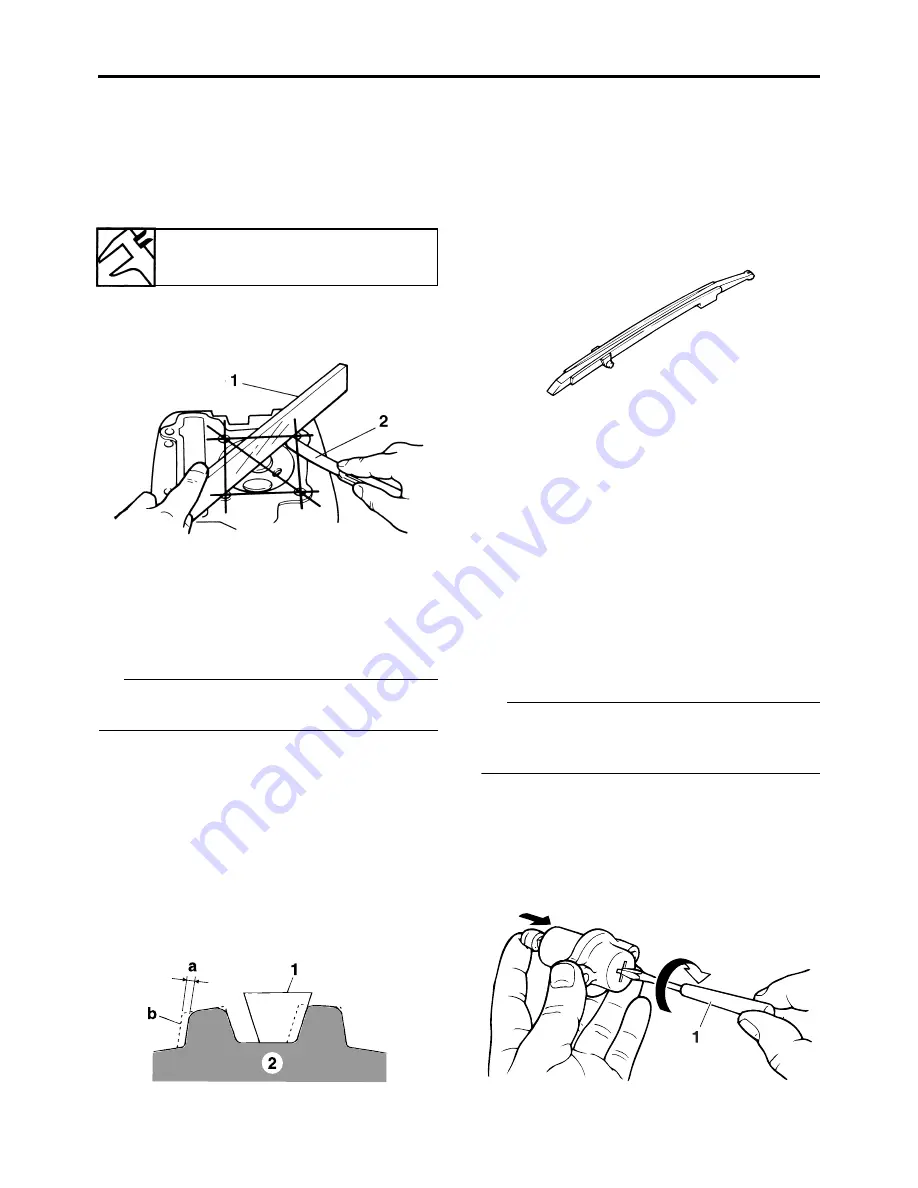
CHECKING THE TIMING CHAIN TEN-
SIONER
1. Check:
• Timing chain tensioner
Cracks/damage
→
Replace.
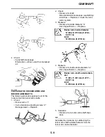
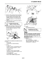
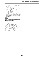
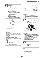
2. Check:
• One-way cam operation
Rough movement
→
Replace the timing
chain tensioner housing.
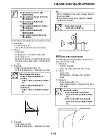
▼▼▼▼▼▼▼▼▼▼▼▼▼▼▼▼▼▼▼▼▼▼▼▼▼▼▼▼▼▼
a. Lightly press the timing chain tensioner rod
into the timing chain tensioner housing by
hand.
TIP
While pressing the timing chain tensioner rod,
wind it clockwise with a thin screwdriver “1”
until it stops.
b. Remove the screwdriver and slowly release
the timing chain tensioner rod.
c. Make sure that the timing chain tensioner
rod comes out of the timing chain tensioner
housing smoothly. If there is rough move-
ment, replace the timing chain tensioner.
▲▲▲▲▲▲▲▲▲▲▲▲▲▲▲▲▲▲▲▲▲▲▲▲▲▲▲▲▲▲
Warpage limit
0.05 mm (0.0020 in)
a. 1/4 tooth
b. Correct
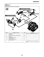
1. Timing chain
2. Camshaft sprocket
Summary of Contents for 2009 YFM25RY
Page 1: ...SERVICE MANUAL YFM25RY YFM25RSEY YFM25RSE2Y 4D3 28197 11 LIT 11616 22 09 2009 ...
Page 8: ......
Page 39: ...LUBRICATION POINTS AND LUBRICANT TYPES 2 20 ...
Page 42: ...LUBRICATION SYSTEM CHART AND DIAGRAMS 2 23 EAS20410 LUBRICATION DIAGRAMS ...
Page 44: ...LUBRICATION SYSTEM CHART AND DIAGRAMS 2 25 ...
Page 46: ...LUBRICATION SYSTEM CHART AND DIAGRAMS 2 27 ...
Page 47: ...LUBRICATION SYSTEM CHART AND DIAGRAMS 2 28 1 Oil cooler 2 Oil hose 1 3 Oil hose 2 ...
Page 48: ...CABLE ROUTING 2 29 EAS20430 CABLE ROUTING ...
Page 50: ...CABLE ROUTING 2 31 ...
Page 52: ...CABLE ROUTING 2 33 ...
Page 54: ...CABLE ROUTING 2 35 ...
Page 56: ...CABLE ROUTING 2 37 ...
Page 58: ...CABLE ROUTING 2 39 ...
Page 60: ...CABLE ROUTING 2 41 ...
Page 62: ...CABLE ROUTING 2 43 ...
Page 65: ......
Page 143: ...HANDLEBAR 4 42 Throttle cable free play 2 0 4 0 mm 0 08 0 16 in ...
Page 162: ...CHAIN DRIVE 4 61 ...
Page 165: ......
Page 240: ...CARBURETOR 6 9 ...
Page 242: ...IGNITION SYSTEM 7 1 EAS27090 IGNITION SYSTEM EAS27100 CIRCUIT DIAGRAM ...
Page 246: ...ELECTRIC STARTING SYSTEM 7 5 EAS27160 ELECTRIC STARTING SYSTEM EAS27170 CIRCUIT DIAGRAM ...
Page 252: ...CHARGING SYSTEM 7 11 EAS27200 CHARGING SYSTEM EAS27210 CIRCUIT DIAGRAM ...
Page 255: ...CHARGING SYSTEM 7 14 ...
Page 256: ...LIGHTING SYSTEM 7 15 EAS27240 LIGHTING SYSTEM EAS27250 CIRCUIT DIAGRAM ...
Page 260: ...SIGNALING SYSTEM 7 19 EAS27270 SIGNALING SYSTEM EAS27280 CIRCUIT DIAGRAM ...
Page 264: ...CARBURETOR HEATING SYSTEM 7 23 EAS27490 CARBURETOR HEATING SYSTEM EAS27500 CIRCUIT DIAGRAM ...
Page 267: ...CARBURETOR HEATING SYSTEM 7 26 ...
Page 268: ...ELECTRICAL COMPONENTS 7 27 EAS27972 ELECTRICAL COMPONENTS ...
Page 270: ...ELECTRICAL COMPONENTS 7 29 EAS27980 CHECKING THE SWITCHES ...
Page 284: ...ELECTRICAL COMPONENTS 7 43 ...
Page 291: ......
Page 292: ...YAMAHA MOTOR CO LTD 2500 SHINGAI IWATA SHIZUOKA JAPAN ...
Page 293: ...WIRING DIAGRAM YFM25RY YFM25RSEY YFM25RSE2Y ...