
CYLINDER HEAD
5-14
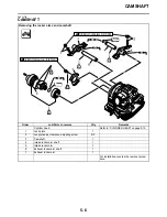
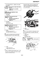
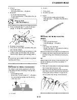
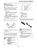
3. Check:
• Cap bolt
• Spring
• One-way cam
• Timing chain tensioner rod
Damage/wear
→
Replace the timing
chain tensioner.
EAS24230
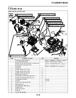
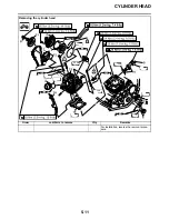
INSTALLING THE CYLINDER HEAD
1. Install:
• Cylinder head gasket
• Dowel pins
2. Install:
• Cylinder head
• Copper washers
• Cylinder head bolts
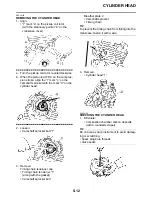
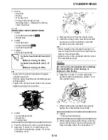
3. Tighten:
• Cylinder head bolts
TIP
• Apply oil to the bearing surface of (upper)
cylinder head bolt.
Further, apply molybdenum disulfide grease
to thread part.
• Tighten the cylinder head bolts in the proper
tightening sequence as shown.
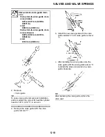
4. Install:
• Camshaft sprocket
• Dowel pin
• Timing chain
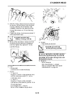
▼▼▼▼▼▼▼▼▼▼▼▼▼▼▼▼▼▼▼▼▼▼▼▼▼▼▼▼▼▼
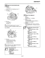
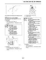
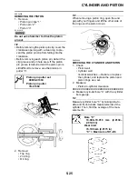
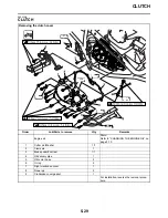
a. Turn the Pickup coil rotor counterclockwise.
b. Align the “I” mark “a” on the Pickup coil
rotor with the stationary pointer “b” on the
crankcase cover.
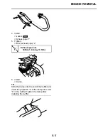
c. Remove the wire from the timing chain.
d. Install the timing chain onto the camshaft
sprocket, and then install the camshaft
sprocket onto the camshaft.
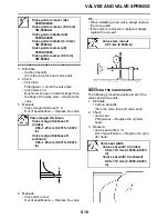
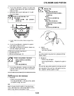
TIP
• When installing the camshaft sprocket, be
sure to keep the timing chain as tight as pos-
sible on the exhaust side.
• Align the pin on the camshaft with the slot in
the camshaft sprocket.
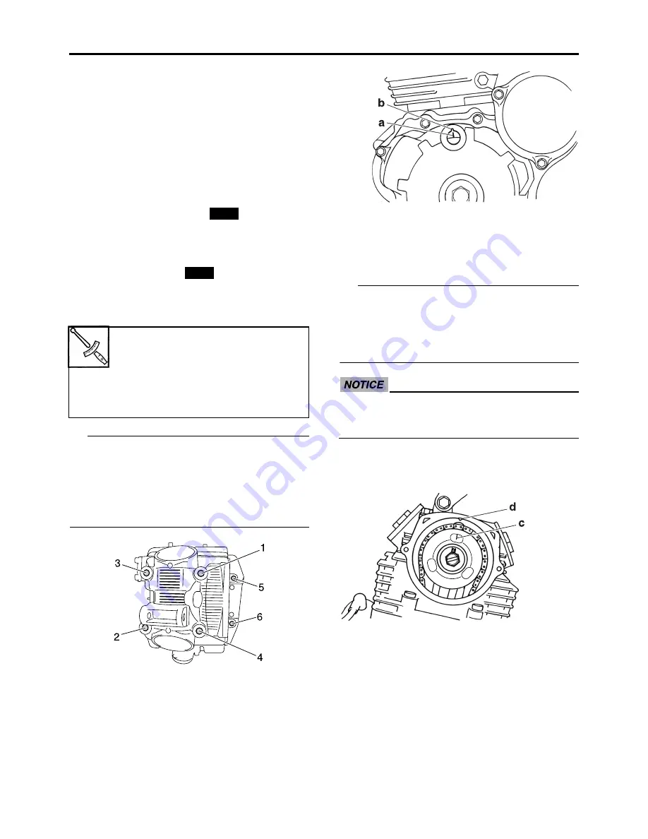
ECA13740
Do not turn the crankshaft when installing
the camshaft(s) to avoid damage or
improper valve timing.
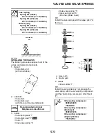
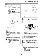
e. Align the “I” mark “c” on the camshaft
sprocket with the stationary pointer “d” on
the cylinder head.
f.
While holding the camshaft, temporarily
tighten the camshaft sprocket bolts.
▲▲▲▲▲▲▲▲▲▲▲▲▲▲▲▲▲▲▲▲▲▲▲▲▲▲▲▲▲▲
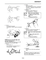
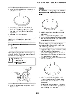
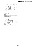
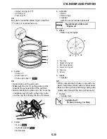
5. Install:
• Timing chain tensioner
▼▼▼▼▼▼▼▼▼▼▼▼▼▼▼▼▼▼▼▼▼▼▼▼▼▼▼▼▼▼
a. While lightly pressing the timing chain ten-
sioner rod by hand, turn the tensioner rod
fully clockwise with a thin screwdriver “1”.
Cylinder head bolt 226 mm (8.90
in)
24 Nm (2.4 m·kg, 18 ft·lb)
Cylinder head bolt 45 mm (1.77
in)
20 Nm (2.0 m·kg, 15 ft·lb)
New
New
Summary of Contents for 2009 YFM25RY
Page 1: ...SERVICE MANUAL YFM25RY YFM25RSEY YFM25RSE2Y 4D3 28197 11 LIT 11616 22 09 2009 ...
Page 8: ......
Page 39: ...LUBRICATION POINTS AND LUBRICANT TYPES 2 20 ...
Page 42: ...LUBRICATION SYSTEM CHART AND DIAGRAMS 2 23 EAS20410 LUBRICATION DIAGRAMS ...
Page 44: ...LUBRICATION SYSTEM CHART AND DIAGRAMS 2 25 ...
Page 46: ...LUBRICATION SYSTEM CHART AND DIAGRAMS 2 27 ...
Page 47: ...LUBRICATION SYSTEM CHART AND DIAGRAMS 2 28 1 Oil cooler 2 Oil hose 1 3 Oil hose 2 ...
Page 48: ...CABLE ROUTING 2 29 EAS20430 CABLE ROUTING ...
Page 50: ...CABLE ROUTING 2 31 ...
Page 52: ...CABLE ROUTING 2 33 ...
Page 54: ...CABLE ROUTING 2 35 ...
Page 56: ...CABLE ROUTING 2 37 ...
Page 58: ...CABLE ROUTING 2 39 ...
Page 60: ...CABLE ROUTING 2 41 ...
Page 62: ...CABLE ROUTING 2 43 ...
Page 65: ......
Page 143: ...HANDLEBAR 4 42 Throttle cable free play 2 0 4 0 mm 0 08 0 16 in ...
Page 162: ...CHAIN DRIVE 4 61 ...
Page 165: ......
Page 240: ...CARBURETOR 6 9 ...
Page 242: ...IGNITION SYSTEM 7 1 EAS27090 IGNITION SYSTEM EAS27100 CIRCUIT DIAGRAM ...
Page 246: ...ELECTRIC STARTING SYSTEM 7 5 EAS27160 ELECTRIC STARTING SYSTEM EAS27170 CIRCUIT DIAGRAM ...
Page 252: ...CHARGING SYSTEM 7 11 EAS27200 CHARGING SYSTEM EAS27210 CIRCUIT DIAGRAM ...
Page 255: ...CHARGING SYSTEM 7 14 ...
Page 256: ...LIGHTING SYSTEM 7 15 EAS27240 LIGHTING SYSTEM EAS27250 CIRCUIT DIAGRAM ...
Page 260: ...SIGNALING SYSTEM 7 19 EAS27270 SIGNALING SYSTEM EAS27280 CIRCUIT DIAGRAM ...
Page 264: ...CARBURETOR HEATING SYSTEM 7 23 EAS27490 CARBURETOR HEATING SYSTEM EAS27500 CIRCUIT DIAGRAM ...
Page 267: ...CARBURETOR HEATING SYSTEM 7 26 ...
Page 268: ...ELECTRICAL COMPONENTS 7 27 EAS27972 ELECTRICAL COMPONENTS ...
Page 270: ...ELECTRICAL COMPONENTS 7 29 EAS27980 CHECKING THE SWITCHES ...
Page 284: ...ELECTRICAL COMPONENTS 7 43 ...
Page 291: ......
Page 292: ...YAMAHA MOTOR CO LTD 2500 SHINGAI IWATA SHIZUOKA JAPAN ...
Page 293: ...WIRING DIAGRAM YFM25RY YFM25RSEY YFM25RSE2Y ...