


FRONT ARMS AND FRONT SHOCK ABSORBER ASSEMBLIES
4-48
EAS29720
REMOVING THE FRONT ARMS
The following procedure applies to both of the
front upper arms and front lower arms.
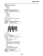
1. Check:
• Front arm free play
▼▼▼▼▼▼▼▼▼▼▼▼▼▼▼▼▼▼▼▼▼▼▼▼▼▼▼▼▼▼
a. Check the front arm side play “A” by mov-
ing it from side to side.
If side play is noticeable, check the bush-
ings.
b. Check the front arm vertical movement “B”
by moving it up and down.
If the vertical movement is tight or rough, or
if there is binding, check the bushings.
▲▲▲▲▲▲▲▲▲▲▲▲▲▲▲▲▲▲▲▲▲▲▲▲▲▲▲▲▲▲
2. Remove:
• Front arm
EAS29730
CHECKING THE FRONT ARMS
The following procedure applies to both of the
front upper arms and front lower arms.
1. Check:
• Front upper arm “1”
• Front lower arm “2”
Bends/damage
→
Replace.
2. Check:
• Bushings “3”
Wear/damage
→
Replace.
EAS29740
HANDLING THE FRONT SHOCK
ABSORBER AND GAS CYLINDER
(For 4D3H, 4D3M)
WARNING
EWA15050
This front shock absorbers and gas cylin-
ders contain highly compressed nitrogen
gas. Before handling the front shock
absorber or gas cylinder, read and make
sure you understand the following informa-
tion. The manufacturer cannot be held
responsible for property damage or per-
sonal injury that may result from improper
handling of the front shock absorber and
gas cylinder.
• Do not tamper or attempt to open the
front shock absorber or gas cylinder.
• Do not subject the front shock absorber
or gas cylinder to an open flame or any
other source of high heat. High heat can
cause an explosion due to excessive gas
pressure
• Do not deform or damage the front shock
absorber or gas cylinder in any way. If the
front shock absorber, gas cylinder or both
are damaged, damping performance will
suffer.
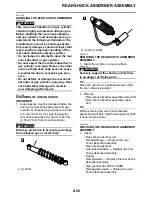
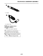
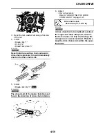
EAS29750
DISPOSING OF A FRONT SHOCK
ABSORBER AND GAS CYLINDER
(For 4D3H, 4D3M)
Gas pressure must be released before dispos-
ing of a front shock absorber and gas cylinder.
To release the gas pressure, use a drill to open
a 2–3 mm (0.08–0.12 in) hole through the gas
valve as shown.
WARNING
EWA13760
Wear eye protection to prevent eye damage
from released gas or metal chips.
Summary of Contents for 2009 YFM25RY
Page 1: ...SERVICE MANUAL YFM25RY YFM25RSEY YFM25RSE2Y 4D3 28197 11 LIT 11616 22 09 2009 ...
Page 8: ......
Page 39: ...LUBRICATION POINTS AND LUBRICANT TYPES 2 20 ...
Page 42: ...LUBRICATION SYSTEM CHART AND DIAGRAMS 2 23 EAS20410 LUBRICATION DIAGRAMS ...
Page 44: ...LUBRICATION SYSTEM CHART AND DIAGRAMS 2 25 ...
Page 46: ...LUBRICATION SYSTEM CHART AND DIAGRAMS 2 27 ...
Page 47: ...LUBRICATION SYSTEM CHART AND DIAGRAMS 2 28 1 Oil cooler 2 Oil hose 1 3 Oil hose 2 ...
Page 48: ...CABLE ROUTING 2 29 EAS20430 CABLE ROUTING ...
Page 50: ...CABLE ROUTING 2 31 ...
Page 52: ...CABLE ROUTING 2 33 ...
Page 54: ...CABLE ROUTING 2 35 ...
Page 56: ...CABLE ROUTING 2 37 ...
Page 58: ...CABLE ROUTING 2 39 ...
Page 60: ...CABLE ROUTING 2 41 ...
Page 62: ...CABLE ROUTING 2 43 ...
Page 65: ......
Page 143: ...HANDLEBAR 4 42 Throttle cable free play 2 0 4 0 mm 0 08 0 16 in ...
Page 162: ...CHAIN DRIVE 4 61 ...
Page 165: ......
Page 240: ...CARBURETOR 6 9 ...
Page 242: ...IGNITION SYSTEM 7 1 EAS27090 IGNITION SYSTEM EAS27100 CIRCUIT DIAGRAM ...
Page 246: ...ELECTRIC STARTING SYSTEM 7 5 EAS27160 ELECTRIC STARTING SYSTEM EAS27170 CIRCUIT DIAGRAM ...
Page 252: ...CHARGING SYSTEM 7 11 EAS27200 CHARGING SYSTEM EAS27210 CIRCUIT DIAGRAM ...
Page 255: ...CHARGING SYSTEM 7 14 ...
Page 256: ...LIGHTING SYSTEM 7 15 EAS27240 LIGHTING SYSTEM EAS27250 CIRCUIT DIAGRAM ...
Page 260: ...SIGNALING SYSTEM 7 19 EAS27270 SIGNALING SYSTEM EAS27280 CIRCUIT DIAGRAM ...
Page 264: ...CARBURETOR HEATING SYSTEM 7 23 EAS27490 CARBURETOR HEATING SYSTEM EAS27500 CIRCUIT DIAGRAM ...
Page 267: ...CARBURETOR HEATING SYSTEM 7 26 ...
Page 268: ...ELECTRICAL COMPONENTS 7 27 EAS27972 ELECTRICAL COMPONENTS ...
Page 270: ...ELECTRICAL COMPONENTS 7 29 EAS27980 CHECKING THE SWITCHES ...
Page 284: ...ELECTRICAL COMPONENTS 7 43 ...
Page 291: ......
Page 292: ...YAMAHA MOTOR CO LTD 2500 SHINGAI IWATA SHIZUOKA JAPAN ...
Page 293: ...WIRING DIAGRAM YFM25RY YFM25RSEY YFM25RSE2Y ...