Electric Chain Hoist CPE/F
5
4.3 ELECTRIC CHAIN HOIST WITH TROLLEY
The units are delivered pre-assembled and are built to fit beam range
A or B which is given on the name plate (Tab. 1). Prior to installation
ensure that the flange width is within the limits indicated.
In 1-strand configuration the suspension hook is to be installed centred
on the marking "1/1" on the main frame assy. , in 2-strand configuration
centred on the marking "2/1",
In 3- and 4-strand configuration the suspension hook is to be installed
centred on the marking "1/1" on the main frame assy.
Attention:
Secure the two suspension pins with locking plate after
assembly.
Selection and calculation of the suitable suspension point and beam
construction are the responsibility of the user.
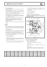
Assembly of the trolley 1,6 - 5 t (see Fig. 10)
1. Unscrew the locking nuts (item 9) and hex nuts (item 2) from the
crossbars (item 1) and remove both side plates (item 6) from the trolley.
2. Measure the flange width of the beam (see Fig. 10 - measure b).
3. Adjust measure B between the shoulders of the round nuts (item 5)
on the threaded crossbars (item 1). Ensure that the 4 bores in the round
nuts face towards the outside. Adjust the measure B to equal measure
b plus 4 mm. Measure A must be 2 mm on either side and the centre
traverse (item 4) must be centred between the round nuts.
4. Replace one side plate (item 6):
Replace one side plate ensuring that the roll pins (item 8) engage into
one of the 4 bores in the round nuts (item 5). To achieve this it may be
necessary to rotate the round nuts slightly.
5. Replace the washers (item 3) and tighten the hex nuts (item 2). Screw
on the locknuts (item 9) finger-tight and tighten a further ¼ to ½ turn.
Attention:
The locknuts must always be fi tted.
No. Description
1 Crossbar
2 Hex. nut
3 Washer
4 Centre traverse
5 Round nut
6 Side plate
7 Trolley wheel
8 Roll pin
9 Locknut
10
Roll pins
B
b
10
5
3
2
9
Fig. 10
A
A
A
B
b
2
9
1
3
4
5
8
6
7
Tab. 1
Capacity
Beam
Flange width
Flange thickness
[kg]
range
[mm]
[mm]
von
bis max.
1.600 - 5.000
A
98
180
27
1.600 - 5.000
B
180
300
27
7.500 - 10.000
B
125
310
40
2
mm
Fig. 9
Summary of Contents for CPEF
Page 15: ...Electric Chain Hoist CPE F 15...
Page 16: ...Electric Chain Hoist CPE F 16...
Page 17: ...Electric Chain Hoist CPE F 17...


