background image

Electric Chain Hoist CPE/F

13

Reassemble the gearbox

Reassemble the gearbox in the reverse order strictly in accordance with 
the sectional drawing.
Special care should be taken for clean and correct installation of planet 
gears (7) with needle bearings (8) in equal sorting and stop washers (6) 
as well as spacer rings (9) in the planet gear carrier (3).
The friction discs (28) on either side of the ring gear (29) must be installed 
oil-soaked (leave in oil for 1 hour before installation).
The exact adjustment of the overload device is only possible when the 
hoist is completely reassembled. Preadjustment of the cup spring (41) 
is made with the fixing screw (42).
After the exact adjustment has been made, the fixing screw (42) is 
secured by means of the ball (46) and the threaded pin (47).

The gear box is to be fi lled with approx. 0,3 Litre gearbox oil 
(CLP 460, DIN 51547)

Afterwards the fill hole can be closed with the screw plug (44) and the 
seal (45).

8.8 MOTOR

Motor

Under normal conditions the motor is practically maintenance-free. Every 
2 ½ years the bearings are to be inspected, cleaned and repacked half-full 
with grease. We recommend K 3 N / KL 3 N DIN 51825 / DIN 51502.

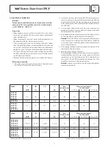
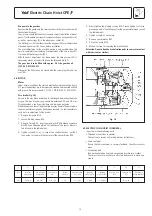
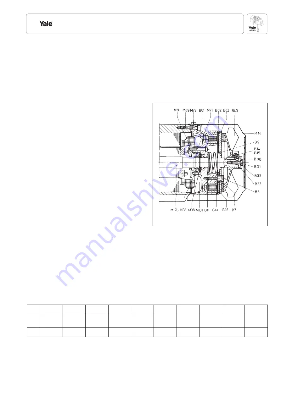
Disc brake (Fig. 18)

Service to the disc brake is reduced to checking and adjusting the brake 
air gap. The disc brake air gap should be between 0,25 and 0,6 mm. 
This guarantees a short reaction time and low noise emission.
When the wear and tear of the brake lining comes down to the point where 
the max. possible air gap has finally been reached, it is indispensible to 
carry out a re-adjustment of the brake:

1.  Remove fan guard M14.

2.  Loosen binding screws B14.

3.  Remove O-ring B62 , insert spacer blocks B40 between armature 

disc B42 und adhesive plate B16 (thickness of the spacer blocks is 
to be found in the table below).

4.  Tighten screws B31, or - in case of two shaft extensions - nut B35 

to an extent as to permit the removal of the spacer blocks B40.

5.  Evenly tighten the binding screws B14. Please tighten first screw 

placed opposite of the fitting key (for the permissible torque consult 
the table below).

6.  Tighten screw B31 once more.

7.  Remove spacer blocks B40.

8.  Put on fan guard M14.

9.  Make a test run for checking the brake funtion.

Attention: Do not allow the brake friction pads to come into contact 
with lubricant or similar!


2 3 4 5 6 7 8 9 10 

11

  Type 

Nominal 

Fan B 43 with 

Spacer block 

Air gap 

Pressure spring 

Tightening 

Tightening 

Adhesive plate 

Threaded pin 

Quantity of


brake torque 

brake lining 

mm 

max. mm 

B9 colour 

torque for B14 

torque for B6 

B16 

B71 

fi tting plate B11


EBF 

20,2 Nm 

WS 5907 

0,25 - 0,3 

0,6 

no colour 

7 - 9 Nm 

7 + 0,5 Nm 

no 

M 5 x 80 

0

8.9 ELECTRIC CHAIN HOIST IN GENERAL

In particular check following parts:

• Threaded connections in general

  Check all nuts, screws and locking devices for tightness.

• Chain  container

  Ensure the chain container is securely fastened. Check for cracks or
 wear.

• Suspension  bolt

(Connection between hoist and suspension bracket resp. trolley)
Check for cracks or wear. Ensure all safety devices are in place and 
secure.

Fig. 18

Summary of Contents for CPEF

Page 1: ...kg 10 000kg Translated Operating and Maintenance Manual COLUMBUS McKINNON Industrial Products GmbH P O Box 11 01 53 D 42301 Wuppertal Germany Yale Allee 30 D 42329 Wuppertal Germany 49 0 202 69359 0 F...

Page 2: ...8 0 37 0 3 0 09 40 40 20 CPE 25 5 CPE F 25 5 2 500 1 40 40 20 2 3 2 3 0 58 4 5 4 5 1 13 1 Am 98 180 or 180 300 1800 or 2000 11 11 2 8 0 37 0 3 0 09 40 40 20 CPE 30 5 CPE F 30 5 3 000 1 25 25 15 2 8 2...

Page 3: ...suspended load see Fig 2 After lifting or tensioning a load must not be left unattended for a longer period of time Start moving the load only after it has been attached correctly and all personnel ar...

Page 4: ...used for lashing purposes sling chain Fig 6 Do not knot or shorten the load chain by using bolts screws screw drivers or other devices Fig 7 Load chains that are integral part of the hoist trolley ar...

Page 5: ...Measure the flange width of the beam see Fig 10 measure b 3 Adjust measure B between the shoulders of the round nuts item 5 on the threaded crossbars item 1 Ensure that the 4 bores in the round nuts f...

Page 6: ...on slotted nut Tip For easier mounting screw one side plate tightly The other side plate is attached loosely Pay attention to the desired position of the drive side 4 Then lift the entire unit to the...

Page 7: ...ngth kW A A 0 50 m 50 100 m 100 150 m CPE F 16 8 CPE F 25 5 CPE F 32 4 0 58 2 3 20 40 1 8 4 4 3 3 5 5 16 1 5 2 5 2 5 CPE F 50 2 CPE F 100 2 2 x 0 58 2 3 20 40 1 8 4 4 4 0 6 8 16 2 5 2 5 CPE F 20 8 CPE...

Page 8: ...ed and approved by a crane expert before initial operation This inspection has to be registered in the crane inspection book The inspection by the crane expert has to be instigated by the operating co...

Page 9: ...son The inspection must determine that all safety devices are present and fully operational and covers the condition of the hoist lifting gear accessories and supporting constructions The service inte...

Page 10: ...irclip with suitable pliers Raise the swivel tube in the direction of the chain and tap out the chain bolt with a drift Attention Do not damage the chain bolt bore 2 Remove the chain end stop Remove t...

Page 11: ...e twisted if the bottom block is rolled over If a strand is twisted disconnect it from the hoist and re thread it correctly In some cases it may be necessary to remove the last link 8 Before initial o...

Page 12: ...rticular around the areas of screwed connections Trolley wheels Visually check for cracks and wear on trolley wheel flanges Grease the transmission Crossbars In particular around threaded areas for cr...

Page 13: ...lining comes down to the point where the max possible air gap has finally been reached it is indispensible to carry out a re adjustment of the brake 1 Remove fan guard M14 2 Loosen binding screws B14...

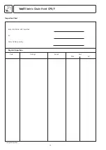
Page 14: ...Electric Chain Hoist CPE F 14 Inspection Chart Inspection before initial operation by Date of initial operation Regular Inspections Date Findings Repair Test Date by competent person...

Page 15: ...Electric Chain Hoist CPE F 15...

Page 16: ...Electric Chain Hoist CPE F 16...

Page 17: ...Electric Chain Hoist CPE F 17...

Page 18: ...hain hoist CPE F Mod CPE F 16 8 Mod CPE F 20 8 Mod CPE F 25 5 Mod CPE F 30 5 Mod CPE F 32 4 Mod CPE F 40 4 Mod CPE F 50 2 Mod CPE F 75 1 6 Mod CPE F 100 2 Capacity 1 600 10 000kg Machine type Electric...

Page 19: ...ettenzug CPE F Mod CPE F 16 8 Mod CPE F 20 8 Mod CPE F 25 5 Mod CPE F 30 5 Mod CPE F 32 4 Mod CPE F 40 4 Mod CPE F 50 2 Mod CPE F 75 1 6 Mod CPE F 100 2 Tragf higkeit 1 600 10 000kg Maschinentyp Elekt...

Page 20: ...d Laser Park Industrial Area Honeydew Phone 00 27 0 11 794 29 10 Fax 00 27 0 11 794 35 60 Web Site www yalejhb co za E mail info yalejhb co za Yale Lifting Solutions Pty Ltd P O Box 592 Magaliesburg 1...

Reviews: