Electric Chain Hoist CPE/F
7
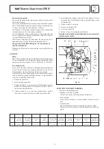
4.4 ELECTRICAL CONNECTION
Attention !
Work at electrical installations may be carried out by el ectrical
experts only. The local regulations have to be strictly observed,
e. g. EN 60204-32 / VDE 0113.
Preparation
• Before beginning work on electrical components the mains current
switch must be switched OFF and secured against unintentionally
being switched back on.
• Before connecting the chain hoist ensure that the electrical data on
the nameplate match the local supply specifications.
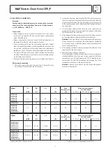
• The mains supply cable must be an insulated cable with 4 flexible
leads. The ground (earth) lead must be longer than the live leads. The
cross-sections and the fusing of the various models and cable lengths
see tables on page 7. Cable ends have to be provided with end sleeves.
• The length of the pendant control cable is determined by working
conditions. Attach the tension relief wire in a manner that the pendant
control cable hangs load-free.
• Wiring and terminal connecting diagrams are included with the hoist.
Mains supply connection
1. The mains supply cable must be connected to the electric chain
hoist before it is connected to the mains supply.
Model P
n
ED I
a
/I
n
I
n
Fuse
Wire cross-section mm
2
(delayed-action)
for wire length
[kW]
[%]
[A]
[A]
0 - 50 m
50 - 100 m
100 - 150 m
CPE 16-8
CPE 25-5
CPE 32-4
2,3
40 4,7 5,3 16* 1,5 1,5 2,5
CPE 50-2
CPE 100-2
2 x 2,3
40
4,7
6,4
16*
2,5
2,5
—
CPE 20-8
CPE 30-5
2,8
25 4,7 6,4 16* 2,5 2,5 —
CPE 40-4
CPE 75-1,6
Model P
n
ED I
a
/I
n
I
n
Fuse
Wire cross-section mm
2
(delayed-action)
for wire length
[kW]
[%]
[A]
[A]
0 - 50 m
50 - 100 m
100 - 150 m
CPE F 16-8
CPE F 25-5
CPE F 32-4
0,58/2,3 20/40 1,8/4,4 3,3/5,5
16*
1,5
2,5
2,5
CPE F 50-2
CPE F 100-2
2 x 0,58/2,3
20/40
1,8/4,4
4,0/6,8
16*
2,5
2,5
—
CPE F 20-8
CPE F 30-5
0,7/2,8 15/25 1,8/4,4 4,0/6,8
16*
2,5
2,5
—
CPE F 40-4
CPE F 75-1,6
all data for 400 V, 3 Phases, 50 Hz
* for direct control, at independent control 10 A
2. On chain hoists with an electric trolley (CPE-VTE) the three phases of
the mains supply are to be connected to the terminal strip within the
terminal box on the trolley. The ground/earth wire is to be connected
to the special ground/ earth connection within the terminal box of
the chain hoist.
3. On chain hoists without electric trolley the mains supply and the
ground/earth wire are to be connected to the terminal strip within
the terminal box of the chain hoist.
4. After removing the terminal box cover, connect the wiring as shown
on the wiring diagram label inside the terminal box cover.
Attention:
On hoists with direct control the ground/earth wire should
always be connected according to the wiring diagram. Should the
mains supply source not provide a ground (earth) connection please
consult the manufacturer.
5. After replacing the terminal box cover, connect the other end of the
supply cable to the mains supply.
6. Check the motor's direction of rotation.
The wiring diagram included has been drawn for a normal, clockwise
rotating installation.Should the user's mains supply not fulfil these
requirements, e.g. the hoist lowers when ''lift'' is selected (or vice
versa) switch the unit OFF immediately and exchange two of the
three phase connections in the mains connection.
Attention:
Under no circumstances may the wiring in the pendant
control be tampered with.
Summary of Contents for CPEF
Page 15: ...Electric Chain Hoist CPE F 15...
Page 16: ...Electric Chain Hoist CPE F 16...
Page 17: ...Electric Chain Hoist CPE F 17...


