background image

Electric Chain Hoist CPE/F

11

chain must be fi tted so that the welds on the standing links face towards 
the chain guide in the housing. Operate the hoist in the lowering direction 
(

-button) to feed the chain through the hoist.

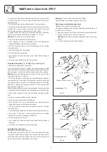
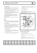
4. Replace chain end stop
Slide the buff er pad over the loose end of the load chain and refi t the 
chain end stop ensuring that at least 1 link remains free (see Fig. 1).

5. Fitting the chain anchor bolt
Inspect the chain anchor bolt for fl aws, cracks or burrs. Enter the last link 
of the other load chain end into the slot in theunderside of the hoist body.

Attention:

 The chain must not be twisted.

Now enter the chain anchor bolt through the side bore. Move the last 
link back and forth while entering the chain anchor bolt to ensure that 
it is not trapped and damaged by the anchor bolt. Secure the anchor 
bolt with the grub screw.

6. Assemble the bottom block
Check the idler sheave for damage. Position the load chain over the 
idler sheave ensuring that the welds on the standing links face away. 
Grease the needle bearings in the bottom block halves. Place the load 
hook assy in the slot provided in one of the bottom block halves and 
push the complete unit onto the idler sheave. Ensuring that the buff er 
pad is situated correctly in its groove replace the second bottom block 
half and secure with the screws.
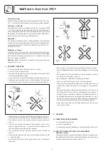
7. Functional test
All units with two or more chain strands must be inspected before every 
operation for twisted or kinked chains. Chains on 2-strand units may 
become twisted if the bottom block is rolled over. If a strand is twisted 
disconnect it from the hoist and re-thread it correctly. In some cases it 
may be necessary to remove the last link.

8. Before initial operation lubricate the unloaded chain and test all hoist 
functions under a no-load condition.

8.4 MAINTENANCE LOAD HOOK

Inspect the hooks for deformation, damage, surface cracks, wear and 
signs of corrosion as required but at least annually. Adverse working 
conditions may dictate shorter periods. Hooks that do not fulfi l all require-
ments must be replaced immediately. Welding on hooks to compensate 
for wear or damage is not permissible. 
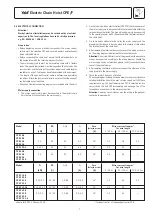
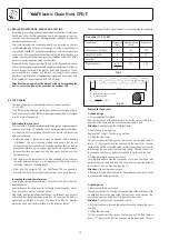
Hooks must be replaced when the mouth of the hook has opened 
more than 10 % (Fig. 15) or the nominal value of other dimensions has 
decreased by 5 % due to wear. Nominal dimensions and wear limits are 
shown in the following table.
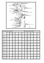
Fig. 16


CPE/F 16 / 20 

CPE/F 32 / 40 / 50


CPE/F 25 / 30 

CPE/F 75 / 100 

 Inspection 

Dim. 

nominal 

min. 

nominal 

min.


value 

value 

value 

value


[mm] 

[mm] 

[mm] 

[mm]

 Hook 

saddle 

b

2

 24 

22,8 

29,5 

28

 Hook 

saddle 

h

2

 35 

33,2 

44,5 

42,3

 Hook 

opening 

a

2

 43 

47,3 54 

59,4

 Hook 

opening 

a

37


40,7 46 50,6

The axial clearance 

Δ

 of the load hook in the direction of force in the 

bottom block and in the cross head assy. (see Fig. 17) has to be deter-
mined additionally at every inspection.
If the measurement is larger than 1 mm a special maintenance service 
is required for the hook head, the balls and the bottom block resp. the 
cross head assy.

The following lower limits are to be obtained:


CPE/F 16 / 20 

 CPE/F 32 / 40 / 50


CPE/F 25 / 30 

  CPE/F 75 / 100

Inspection 

Dim. 

min. Dim. in mm 

min. Dim. in mm

Diameter of ball 


4,75 

5,7

Hook head 

α

 6,3 

7,9

Bottom block 

β

 8 

9,2

Axial clearance 

Δ


1 1

Fig. 17

Summary of Contents for CPEF

Page 1: ...kg 10 000kg Translated Operating and Maintenance Manual COLUMBUS McKINNON Industrial Products GmbH P O Box 11 01 53 D 42301 Wuppertal Germany Yale Allee 30 D 42329 Wuppertal Germany 49 0 202 69359 0 F...

Page 2: ...8 0 37 0 3 0 09 40 40 20 CPE 25 5 CPE F 25 5 2 500 1 40 40 20 2 3 2 3 0 58 4 5 4 5 1 13 1 Am 98 180 or 180 300 1800 or 2000 11 11 2 8 0 37 0 3 0 09 40 40 20 CPE 30 5 CPE F 30 5 3 000 1 25 25 15 2 8 2...

Page 3: ...suspended load see Fig 2 After lifting or tensioning a load must not be left unattended for a longer period of time Start moving the load only after it has been attached correctly and all personnel ar...

Page 4: ...used for lashing purposes sling chain Fig 6 Do not knot or shorten the load chain by using bolts screws screw drivers or other devices Fig 7 Load chains that are integral part of the hoist trolley ar...

Page 5: ...Measure the flange width of the beam see Fig 10 measure b 3 Adjust measure B between the shoulders of the round nuts item 5 on the threaded crossbars item 1 Ensure that the 4 bores in the round nuts f...

Page 6: ...on slotted nut Tip For easier mounting screw one side plate tightly The other side plate is attached loosely Pay attention to the desired position of the drive side 4 Then lift the entire unit to the...

Page 7: ...ngth kW A A 0 50 m 50 100 m 100 150 m CPE F 16 8 CPE F 25 5 CPE F 32 4 0 58 2 3 20 40 1 8 4 4 3 3 5 5 16 1 5 2 5 2 5 CPE F 50 2 CPE F 100 2 2 x 0 58 2 3 20 40 1 8 4 4 4 0 6 8 16 2 5 2 5 CPE F 20 8 CPE...

Page 8: ...ed and approved by a crane expert before initial operation This inspection has to be registered in the crane inspection book The inspection by the crane expert has to be instigated by the operating co...

Page 9: ...son The inspection must determine that all safety devices are present and fully operational and covers the condition of the hoist lifting gear accessories and supporting constructions The service inte...

Page 10: ...irclip with suitable pliers Raise the swivel tube in the direction of the chain and tap out the chain bolt with a drift Attention Do not damage the chain bolt bore 2 Remove the chain end stop Remove t...

Page 11: ...e twisted if the bottom block is rolled over If a strand is twisted disconnect it from the hoist and re thread it correctly In some cases it may be necessary to remove the last link 8 Before initial o...

Page 12: ...rticular around the areas of screwed connections Trolley wheels Visually check for cracks and wear on trolley wheel flanges Grease the transmission Crossbars In particular around threaded areas for cr...

Page 13: ...lining comes down to the point where the max possible air gap has finally been reached it is indispensible to carry out a re adjustment of the brake 1 Remove fan guard M14 2 Loosen binding screws B14...

Page 14: ...Electric Chain Hoist CPE F 14 Inspection Chart Inspection before initial operation by Date of initial operation Regular Inspections Date Findings Repair Test Date by competent person...

Page 15: ...Electric Chain Hoist CPE F 15...

Page 16: ...Electric Chain Hoist CPE F 16...

Page 17: ...Electric Chain Hoist CPE F 17...

Page 18: ...hain hoist CPE F Mod CPE F 16 8 Mod CPE F 20 8 Mod CPE F 25 5 Mod CPE F 30 5 Mod CPE F 32 4 Mod CPE F 40 4 Mod CPE F 50 2 Mod CPE F 75 1 6 Mod CPE F 100 2 Capacity 1 600 10 000kg Machine type Electric...

Page 19: ...ettenzug CPE F Mod CPE F 16 8 Mod CPE F 20 8 Mod CPE F 25 5 Mod CPE F 30 5 Mod CPE F 32 4 Mod CPE F 40 4 Mod CPE F 50 2 Mod CPE F 75 1 6 Mod CPE F 100 2 Tragf higkeit 1 600 10 000kg Maschinentyp Elekt...

Page 20: ...d Laser Park Industrial Area Honeydew Phone 00 27 0 11 794 29 10 Fax 00 27 0 11 794 35 60 Web Site www yalejhb co za E mail info yalejhb co za Yale Lifting Solutions Pty Ltd P O Box 592 Magaliesburg 1...

Reviews: