


Electric Chain Hoist CPE/F
12
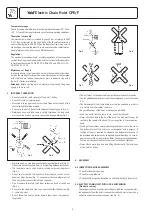
8.6 MAINTENANCE OF OVERLOAD PROTECTION DEVICE
Overload protection device
The unit is equipped with an overload protection device as standard.
This device is factory set to min. 125 % + 10 % of the rated capacity and
prevents reliably overloading of the hoist during lifting of loads.
Adjustment and testing of the overload device may only be carried out
by authorized competent persons.
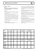
The force-limit factor according EN 14492-2:2006 amounts
φ
DAL
= 1,35.
The maximum force occuring when the rated capacity limiter operates
will be calculated as:
F
LIM
= (
φ
DAL
x m
RC
+ m
H
- m
RC
) x g
φ
DAL
= 1,35
m
RC
= Rated capacity of the hoist [kg]
m
H
= Hoist load [kg]
Hoist load m
H
: Load which includes all the masses of a load equal to the
rated capacity of the hoist, the hoist medium and the fi xed load lifting
attachments, e. g. hooks, grabs, magnets, lifting beams, vacuum lifters.
g = Acceleration due to gravity (9,81) [m/s
2
]
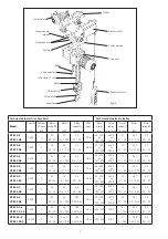
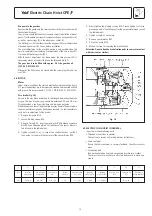
Adjustment of overload device (Fig. 26)
Attention:
The adjustment of the overload device may only be done by
authorized, competent personnel.
Attention:
During this job the hoist remains operable which can result
in danger of injury by rotating parts.
• Loosen the 4 screws (52) of the gear box cover (51).
• Loosen the threaded pin (47) which is pressing the ball (46) on the
cover to lock the straining screw (42).
• Check the adjustment with a suitable load (min. 125 % of the rated
capacity).
• Increase the moment of friction by turning the straining screw (42) in
clockwise direction until the load is raised.
Attention:
The max. operating time of the overload device is 60
seconds. Thereafter the unit has to cool down to room temperature
(min. 20 minutes).
• Screw in the threaded pin (47) (secured with Loctite
®
243)
• Screw on the gear box cover (51) with the cylinder screws (52).
8.7 MAINTENANCE OF GEARBOX
The gearbox is practically maintenance-free. Service is therefore reduced
to changing the oil.
Oil change
The gearbox oil should be changed after every 5 years, however, latest
after 400 operating hours (oil volume: ca. 0,3 Litre).
Attention:
During oil change the electric power supply must be shut off .
8.5 MAINTENANCE TROLLEYS
In particular check following parts:
• Side plate: For cracks or deformation in particular around the areas
of screwed connections.
• Trolley wheels: Visually check for cracks and wear on trolley wheel
flanges. Grease the transmission.
• Crossbars: In particular around threaded areas for cracks.
• Fasteners: Check nuts, screws and locking devices for tightness.
Disassemble the gear cover (item 51) by removing the cylinder screws
(item 52). and unscrew the screw plug (item 44). Place the hoist hori-
zontally and turn so that the oil can drain from the fill hole into a suitable
container (approx. 30 minutes).
Replenish the gearbox oil. We recommend a mineral oil viscosity class
ISO-VG 460, e. g. FINA GIRAN L 460. Finally re-adjust the overload
protection device.
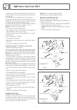
Disassemble/Assemble The Gearbox
Attention:
The gearbox has oil lubrication
Disassembling
1. Pull the coupling (50) off the gear shaft (35). Loosen screws (52)
and remove gearbox cover (51).
2. Remove screw plug (44) and seal (45).
3. Place gearbox upside down and drain oil from the fill hole into a
suitable container.
4. Loosen threaded pin (47), remove ball (46) and unscrew fixing screw
(42).
5. Remove cup springs (41).
6. Loosen locking screw (38) and remove locking bolt (39).
7. Loosen snap ring (37), remove bearing plate (33) and ball bearing
(36). Remove snap ring (34) and press ball bearing (36) out of
bearing plate (33). Remoove snap ring (37) from gear shaft (35).
8. Remove friction discs (28) and ring gear (29).
9. Remove planet gears (32), needle bearings (31), stop washers (30)
as well as planet gear carrier assy (27) and pinion (26). Pull out
gear shaft (35).
10. Remove threaded pin (17).
11. Press out remaining gears in the housing (1) in direction of the flange.
Light blows with a rubber hammer in axial direction onto the rim of
the housing (flange side) may be helpful to loosen the bearing race
(15).
12. Remove planet gears (25), needle bearings (24) and stop washers
(23) from planet gear carrier (22).
13. Pull planet gear carrier (22) and pinion (21) out of planet gear carrier
(3).
14. Remove ball bearing (20) and bearing race (15) from planet gear
carrier (3).
15. Remove snap ring (11) from planet gear carrier (3) and press out
planet gear shaft (10).
16. Remove planet gears (7), needle bearings (8), stop washers (6) and
spacer rings (9).
17. Remove bearing (5) and packing rings (4).
After cleaning, inspection and replacement of all worn parts re-assembly
can be started.
Parts subject to wear are:
Stop washers (6, 23, 30), needle bearings (8, 24, 31), O-rings and
packing rings (4, 16, 18, 43) as well as the seal (45).
Summary of Contents for CPEF
Page 15: ...Electric Chain Hoist CPE F 15...
Page 16: ...Electric Chain Hoist CPE F 16...
Page 17: ...Electric Chain Hoist CPE F 17...


