Alyza IQ PO4
Commissioning
49
ba76201d03
05/2020
Installation on a
mounting stand or
rail mounting
accessory
Installation on a
wall
Installing the
canopy and
terminal
5
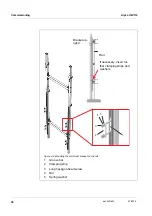
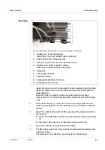
Position the second bracket (5) on the mounting stand and insert the
ends of the bracket in the bore holes of the angle bracket.
Fix the angle bracket (6) to the bracket loosely with 2 nuts.
1
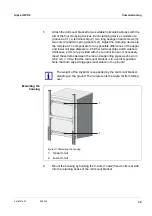
Screw the mounting sheet (4) to both brackets (2, 6) with 4 hexagon
socket screws and nuts.
2
On the rear side of the mounting sheet (4), plug four screws into the drill-
ings (3) far enough so that they can be seen on the other side.
3
Hold the mounting sheet (4) in the desired height and tighten the 4 nuts
at the brackets (1, 3) until the terminal holder is safely mounted.
1
On the rear side of the mounting sheet (4), plug four screws into the drill-
ings (3) far enough so that they can be seen on the other side.
2
Screw the mounting sheet (4) to the wall.
1
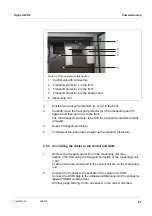
Tighten the 4 screws to fix the canopy to the mounting sheet (4).
At the bottom of the mounting sheet, keep some space free for the
cabling of the power supply.
2
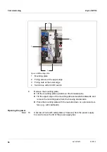
Mount an IQ module (e.g. MIQ/JB, DIQ/S 28X, ...) to the canopy (see
IQ S
ENSOR
N
ET
system operating manual).
3
Dock a terminal onto the MIQ/JB as necessary.
4
Connect the IQ S
ENSOR
N
ET
cable of the Alyza IQ to the IQ module (see
IQ S
ENSOR
N
ET
system operating manual).
5
If necessary, connect the IQ module with a second IQ S
ENSOR
N
ET
cable to integrate the Alyza IQ into an existing IQ S
ENSOR
N
ET
(see
IQ S
ENSOR
N
ET
system operating manual).
Summary of Contents for WTW Alyza IQ PO4
Page 171: ......


