Commissioning
Alyza IQ PO4
56
ba76201d03
05/2020
Connecting the
intake lines and
return lines
12
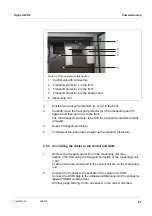
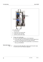
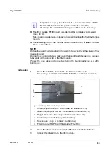
On the underside of the power supply box, remove the protective plugs
from those cable glands you need to connect the cables.
Unused cable glands have to be closed with the supplied black plugs.
13
Only for variants with 2 sample channels:
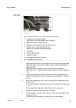
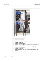
Run the intake line for channel 2 through the big rear cable gland (from
the rear housing panel) at the housing bottom.
– The sleeve tube should protrude into the interior approx. 1 cm to pro-
tect the intake line from being damaged (see figure 3-25).
– Fix the sleeve tube with the cable gland.
14
Run the intake line for channel 1 through the second big cable gland
(from the rear housing panel) at the housing bottom.
– The sleeve tube should protrude into the interior approx. 1 cm to pro-
tect the intake line from being damaged (see figure 3-25).
– Fix the sleeve tube with the cable gland.
15
Run the return line for waste from the measuring unit through the next
big cable gland at the housing bottom.
– The sleeve tube should end flush with the tube inside the housing so
that a collection funnel can be installed.
– Fix the sleeve tube with the cable gland.
The liquid in the return line must be able to flow freely (steady
slope). Do not immerse the end of the return line in water.
16
To guide the sample return into the basin and dispose of the chemicals
waste separately:
Install the collection funnel (WF Set) (see section 3.3.15 Mounting the
WF Set (collection funnel for sample overflow),
Summary of Contents for WTW Alyza IQ PO4
Page 171: ......


