Overview
Alyza IQ PO4
12
ba76201d03
05/2020
Power supply and
communication
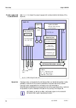
12 shows the power supply and communication interfaces of the
Alyza IQ.
Operation
The Alyza IQ is connected to the IQ S
ENSOR
N
ET
via the IQ S
ENSOR
N
ET
cable
(SNCIQ) connected to the control unit ACM and conducted to the outside.
The Alyza IQ is operated with a terminal on the IQ S
ENSOR
N
ET
.
If maintenance activities are being carried out on the open Alyza IQ, a terminal
for operation must be installed or docked in the vicinity of the Alyza IQ.
figure 1-3 Block diagram Alyza IQ
Alyza IQ
Photometer unit
(Options)
H1
Line voltage
input
P
p1
H4
IQ Sensor Net (data + power)
e.g. SN 18110005
Control unit ACM
IQ Sensor Net interface
e.g. SN 18110258
Legend:
P , P
Filtration pumps
p1
P2
H1 ... H4 Heat tracing
(feed lines, return lines)
Control unit ACS
24 V DC
Drive unit
MultiPort valve
USB
...
e.g. SN 18110005
Ethernet
Measuring unit
Daten+Energie
P
p2
Switch box
On/Off
Power supply box
Overload protection
Line power filter
Power supply
Outputs
Information on IQ S
ENSOR
N
ET
terminals is given in the relevant
IQ S
ENSOR
N
ET
system operating manual.
Summary of Contents for WTW Alyza IQ PO4
Page 171: ......


