


XSD27ZIR
16
SYSTEM MENU
■
SYSTEM MENU OPTIONS
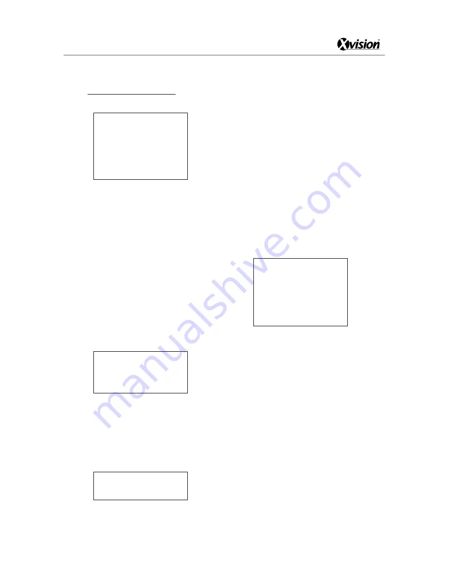
<Main Menu>
<System >
Site Info
Display Setup
Bootup Screen
Password
Set Default
System Reboot
Back
SYSTEM INFO includes following settings.
<Site Info>
Dome ID, name, broadcast address.
<Display Setup>
Screen display
<Bootup Screen>
Display boot-up information
<Password>
Change password
<Set Default>
Restore factory default settings
<Reboot System>
Reboot dome system
■
SITE INFO
<Main Menu>
<System >
<Site Info>
Site ID: 007
Name: Is Bond
Broadcast Add: 255
Back
<Site ID>
Shows the current dome’s ID. Each dome has its unique
ID. ID ranges from 001 to 254. NOTE: <Site ID> can be
set by menu only when DIP switch is set to
‘programmable ID’.
Move the cursor to <Site ID> and then move the
joystick right to enter dome ID setting, sub-menu as
follow.
Site S/N :8888899999
Input S/N:0000000000
Back
Move the cursor to <Input S/N> then move the joystick
right, input the serial number according to the <Site
S/N>, and then move the joystick left to exit setting. Go
to <Back>, and move joystick right to exit. Finally,
move joystick up or down to select desired ID number.
Move the joystick left to save the settings.
<Name>
<Name> refers to the title of the dome. Assign a dome
name to remember which dome it is.
<Broadcast Add>
Used to set the broadcast ID number. The ID functions
the same as dome’s site ID, default setting is 255. The
dome responds to commands sent to either ID. Refer to
<Changing Values> to learn how to set the broadcast
address)
Select BACK to return to upper menu.
■
DISPLAY SETUP
<Main Menu>
<System >
<Display
Setup>
Site Name: On
Preset Title: On
Cruise Title: On
Pattern Name: On
Orientation: On
Zone Name: On
Cross Curser: On/Off
Back
The on screen display can be customized using this
menu.
<Site Name>
Choose to display the site name
<Preset Title>
Choose to display cruise title when the dome is in
cruise mode
<Cruise Title>
Choose to display preset title when calling preset
<Pattern Name>
Choose to display pattern title when the dome is
replaying pattern sequences
<Orientation>
Choose to display the current lens pointing
direction
<Zone Name>
Choose to display the current zone title
Select BACK to return to upper menu.
Summary of Contents for XSD27ZIR
Page 13: ...XSD27ZIR 13 SYSTEM CONNECTION ...
Page 35: ...XSD27ZIR 35 ...


