XSD27ZIR
22
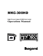
<Edit>
Edit presets and corresponding dwell times in a tour as
follows:
Preset-Dwell
001-001 002-004 003-002
004-001 000-001 000-001
000-001 000-001 000-001
000-001 000-001 000-001
000-001 000-001 000-001
000-001 000-001 000-001
000-001 000-001 000-001
000-001 000-001 000-001
000-001 000-001 000-001
Save And Back
Cancel And Back
The format for the information is displayed as:
Preset number-Dwell time
For example 003-02 means go to preset 003 and dwell
for 2 seconds. Move joystick left or right to select
editing item. Move up or down to change the value.
In the above example the tour starts from preset 1
dwells for 1 second, then goes to preset 2 dwell for 5
seconds, then preset 3 for 2 seconds and finally preset
4 for 1 second.
<
Save and Back
> Save the tour and exit
<
Cancel and Back
> Quit without saving
NOTE: When a preset dwell time is set 0, system will
skip that preset. System will consider preset 0 as the
end of a tour.
NOTE: No delete function applied to tour, edit it again
to replace the previous data.
<Test>
Select to run the current tour once. Use this function to
check the tour.
<Run>
Select to run the current tour continuously. The system
will loop the tour.
<Back>
Select to go Back to the upper menu.
■
CRUISE
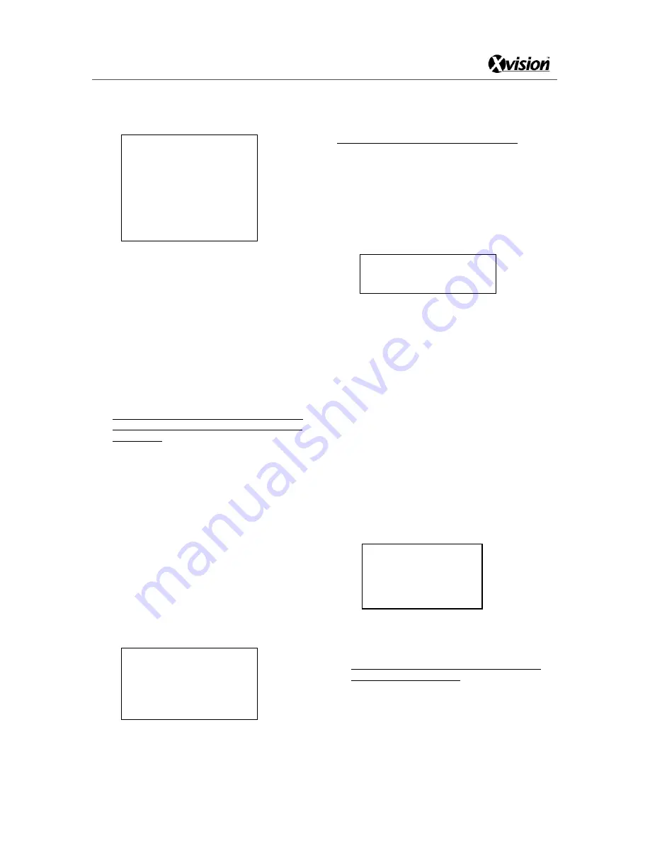
<Main Menu>
<Auto Running>
<Cruise>
Cruise Number : 001
Left Position
Right Position
Default Speed: 001
Run
Back
The dome camera can pan from one left point to right
point and then pan back. NOTE: Camera pans only.
NOTE: If the speed dome has been zoomed in and
<Cruise> is selected, the camera will keep that zoom
throughout the camera’s movement.
The speed dome has a maximum of 4 cruise lines.
<Cruise Number>
Displays the current auto scan number. The value can
be set to 001~004. Move the joystick right, then up or
down to select values.
<Left Position>
Select to set the position of site A. The following menu
will pop up.
Call Preset 1 To
Confirm…
Move the camera to the desired position and call preset
1 to save.
<Right Position>
Select to set the position of site B. Set it in the same
way as <Left Position>.
<Cruise Speed>
Select to set the scanning speed (camera movement
speed). Values can be set ranging from 001 to 255, the
greater number represents the higher speed. Move
joystick right to select, up or down to change the value.
<Run>
Start the current auto scan (001~004)
<Back>
Select to go back to the upper menu.
■
PATTERN
<Main Menu>
<Auto Running>
<Pattern>
Pattern is a replay of recorded irregular pan/tilt/zoom
movements. It is useful when repeating variable speed
movement of the pan/tilt/zoom.
Note: There can be as many as 4 patterns recorded,
each no more than 3 minutes.
<Pattern Number>
Displays the pattern number, value options are 001
~
004.
Pattern Number: 001
Record
Test
Run
Back
Summary of Contents for XSD27ZIR
Page 13: ...XSD27ZIR 13 SYSTEM CONNECTION ...
Page 35: ...XSD27ZIR 35 ...