background image

LIMITED PARTS WARRANTY 

XFYRE – TYPE H and WH 

MODELS 300A-850A

RAYPAK, INC

• 2151 Eastman Avenue • Oxnard, CA 93030-9786 • (805) 278-5300 • Fax (800) 872-9725 • www.raypak.com

SCOPE

Raypak, Inc. (“Raypak”) warrants to the original owner that all parts of this heater which are actually manufactured by Raypak will be free from failure 

under normal use and service for the specified warranty periods and subject to the conditions set forth in this Warranty. Labor charges and other 

costs for parts removal or reinstallation, shipping and transportation are not covered by this Warranty but are the owner’s responsibility. 

HEAT EXCHANGER WARRANTY

Space Heating (Closed Loop System)

Ten (10) year limited warranty from date of heater installation. This warranty applies only to boilers utilized in closed loop heating systems and hot 

water supply boilers that have been properly installed based upon manufacturer’s installation instructions. 

Year of Claim 


0-5 


9

Percentage to be paid 

by purchaser 


0 % 


20% 


40% 


60% 


80% 

Thermal Shock Warranty

Twenty  (20)  years  from  date  of  heater  installation  against  “Thermal  Shock”  (excluded,  however,  if  caused  by  heater  operation  at  large  changes 

exceeding 150°F between the water temperature at intake and heater temperature, or operating at heater temperatures exceeding 215°F). 

ANY OTHER PART MANUFACTURED BY RAYPAK

One (1) year warranty from date of heater installation, or eighteen (18) months from date of factory shipment based on Raypak’s records, whichever 

comes first. 

SATISFACTORY  PROOF  OF  INSTALLATION  DATE,  SUCH  AS  INSTALLER  INVOICE,  IS  REQUIRED.  THIS 

WARRANTY WILL BE VOID IF THE HEATER RATING PLATE IS ALTERED OR REMOVED. 

ADDITIONAL WARRANTY EXCLUSIONS

This warranty does not cover failures or malfunctions resulting from: 

1. Failure to properly install, operate or maintain the heater in accordance with our printed instructions provided; 

2. Abuse, alteration, accident, fire, flood and the like; 

3. Sediment or lime build-up, freezing, or other conditions causing inadequate water circulation; 

4. High velocity flow exceeding heater design rates; 

5. Failure of connected system devices, such as pump or controller; 

6. Use of non-factory authorized accessories or other components in conjunction with the heater system; 

7. Failing to eliminate air from, or replenish water in, the connected water system; 

8. Chemical contamination of combustion air or use of chemical additives to water. 

PARTS REPLACEMENT

Under  this  Warranty,  Raypak  will  furnish  a  replacement  for  any  failed  part.  The  failed  part  must  first  be  returned  to  Raypak  if  requested,  with 

transportation charges prepaid, and all applicable warranty conditions found satisfied. The replacement part will be warranted for only the unexpired 

portion of the original warranty. Raypak makes no warranty whatsoever on parts not manufactured by it, but Raypak will apply any such warranty as 

may be provided to it by the parts manufacturer. 

TO MAKE WARRANTY CLAIM

Promptly  notify  the  original  installer,  supplying  the  model  and  serial  numbers  of  the  unit,  date  of  installation  and  description  of  the  problem.  The 

installer must then notify his Raypak distributor for instructions regarding the claim. If either is not available, contact Service Manager, Raypak, Inc., 

2151  Eastman  Avenue,  Oxnard,  CA  93030  or  call  (805)  278-5300.  In  all  cases  proper  authorization  must  first  be  received  from  Raypak  before 

replacement of any part. 

EXCLUSIVE WARRANTY - LIMITATION OF LIABILITY

This is the only warranty given by Raypak. No one is authorized to make any other warranties on Raypak’s behalf. THIS WARRANTY IS IN LIEU OF 

ALL OTHER WARRANTIES, EXPRESS OR IMPLIED, INCLUDING BUT NOT LIMITED TO IMPLIED WARRANTIES OF MERCHANTABILITY AND 

FITNESS  FOR  A  PARTICULAR  PURPOSE.  RAYPAK’S  SOLE  LIABILITY  AND  THE  SOLE  REMEDY  AGAINST  RAYPAK  WITH  RESPECT  TO 

DEFECTIVE PARTS SHALL BE AS PROVIDED IN THIS WARRANTY. IT IS AGREED THAT RAYPAK SHALL HAVE NO LIABILITY, WHETHER 

UNDER  THIS  WARRANTY,  OR  IN  CONTRACT,  TORT,  NEGLIGENCE  OR  OTHERWISE,  FOR  ANY  SPECIAL,  CONSEQUENTIAL,  OR 

INCIDENTAL DAMAGE, INCLUDING DAMAGE FROM WATER LEAKAGE. Some states do not allow limitations on how long an implied warranty 

lasts, or for the exclusion of incidental or consequential damages. So the above limitation or exclusion may not apply to you. 

This  Limited  Warranty  gives  you  specific  legal  rights.  You  may  also  have  other  rights  which  may  vary  from  state  to  state.  We  suggest  that  you 

complete  the  information  below  and  retain  this  certificate  in  the  event  warranty  service  is  needed.  Reasonable  proof  of  the  effective  date  of  the 

warranty (date of installation) must be presented; otherwise, the effective date will be based on the date of manufacture plus thirty (30) days. 

Original Owner 


Model Number 


Serial Number 

Mailing Address 


Date of Installation 

City 


State 


Zip Code   

Installation Site 

Daytime Telephone Number   


Contractor/Installer 

58

Summary of Contents for 300A

Page 1: ...vapors and liquids or other combustible materials in the vicinity of this or any other appliance To do so may result in an explosion or fire WHAT TO DO IF YOU SMELL GAS Do not try to light any applia...

Page 2: ...ge 17 Table J on page 18 Table L on page 19 Fig 22 on page 28 Termination on page 29 Fig 23 on page 30 Wiring Diagram on page 44 Table Y on page 47 Additions Table G on page 13 Warning on page 29 Ther...

Page 3: ...ons 21 Venting 25 Venting Installation Tips 28 Venting Configurations 28 Condensate Management 33 Outdoor Installation 34 Controls 34 Operating Instructions 37 WIRING DIAGRAM 44 START UP 45 Pre Start...

Page 4: ...WARNING CALIFORNIA PROPOSITION 65 This product contains chemicals known to the State of California to cause cancer birth defects or other reproductive harm WARNING Risk of electrical shock More than o...

Page 5: ...k s standard war ranties Model Identification The model identification number and heater serial number are found on the heater rating plate located on the upper rear jacket panel The model number has...

Page 6: ...ig 2 Component Locations Top Fig 3 Component Locations Rear Model No MBTUH Input Water conn NPT Gas conn NPT Vent Size inches Max Min N P Flue Intake 300A 300 60 1 1 2 3 4 3 4 4 4 400A 399 80 2 1 1 4...

Page 7: ...water for use by individuals a thermostatically controlled mixing valve for reducing point of use water temperature is recommended to reduce the risk of scald injury Contact a licensed plumber or the...

Page 8: ...be located at least 18 in above the floor In addition the heater shall be installed such that the gas ignition system components are protected from water dripping spraying rain etc during appliance op...

Page 9: ...ll local codes NOTE Use of this boiler in construction areas where fine particulate matter such as concrete or dry wall dust is present may result in damage to the boiler that is not covered by the wa...

Page 10: ...ft 1 2m below or to side of opening 1 ft 30 cm above opening 3 ft 91 cm K Clearance to mechanical air supply inlet 3 ft 91 cm above if within 10 ft 3m horizontally 6 ft 1 83m L Clearance above paved...

Page 11: ...of the heater when the combustion air ducting kit is installed using three or four sheet metal screws not supplied equally positioned around the circumference of the duct The screws and duct connectio...

Page 12: ...be drawn from the air outside of the building the mechanical equip ment room must communicate directly with the outdoors Canadian Installations 14 000 BTUH 160 mm2 per kW in excess of 1 million BTUH T...

Page 13: ...valve Carefully fill the rest of the system making sure to eliminate any entrapped air by using high point vents Close feed valve Test at standard operating pressure for at least 24 hours 2 Make sure...

Page 14: ...70 34 19 H7 850A 80 40 53 17 46 12 41 10 39 80 40 20 Fig 6 Air Separation Expansion Tank Air Separation Expansion Tank All heaters should be equipped with a properly sized expansion tank and air separ...

Page 15: ...or heat is present The Boiler Pump P1 runs during any call for heat The Indirect DHW Pump P3 runs during an indirect call for heat with no off delay The Boiler Pump P1 and System Pump P2 delay off as...

Page 16: ...whenever the system is enabled The Boiler Pump is delayed off after the Tank Target temperature is achieved and as user defined in the ADJUST menu Domestic Hot Water When designing the water piping sy...

Page 17: ...21 9 WH7 400A 1630 1 2 39 21 0 19 4 WH7 500A 1630 1 2 48 20 7 19 8 WH7 700A 1634 1 69 36 0 19 3 WH7 850A 1634 1 69 36 0 23 4 WARNING Plumbing between the heater and tank in excess of 75 equivalent fee...

Page 18: ...e heater gas controls When connecting additional gas utilization equipment to the gas piping system the existing piping must be checked to determine if it has adequate capacity for the combined load T...

Page 19: ...6 220 310 795 850A 25 55 55 125 175 450 for pilot duty only XFyre heaters may power up to 2 pumps directly Install a circuit breaker sized sufficient ly for both the heater and the pump s An indirect...

Page 20: ...dicated circuit breaker should be provided and sized for the heater and all pumps powered through the heater 2 Turn off all power to the heater Verify that power has been turned off by testing with a...

Page 21: ...LARM CONTROL SENSOR WIRING HIGH VOLTAGE POWER AND PUMP WIRING LOCATION RATING PLATE SUGGESTED ROUTING OF SENSOR CONTROL WIRING Fig 14 Rear Wiring Location Fig 16 XFyre Single Heater Control PLATFORM I...

Page 22: ...to ensure nei ther of these terminals becomes connected to ground Wiring the Optional 0 10 Volt Building Control Signal 1 A signal from an energy management system may be connected to the XFyre boiler...

Page 23: ...voltage 120 volt or greater wiring Raypak recommends that the total maxi mum length of each set of communication bus cables not exceed 200 feet 3 Route the FT_BUS wires from the front along the top ra...

Page 24: ...Fig 16 This connection must be pro vided through dry contacts closure NOTE This dry contacts closure can come from a room thermostat or a remote relay No power of any kind should be applied to either...

Page 25: ...nsate The vent adapter kit supplied by Raypak includes a higher temperature rated vent limit Vent installation shall be in accordance with Part 7 Venting of Equipment of the NFGC ANSI Z223 1 NFPA 54 S...

Page 26: ...area where condensate or vapor could create a nuisance or hazard or could be detrimen tal to the operation of regulators relief valves or other equipment 6 Locate and guard vent termination to preven...

Page 27: ...tion Code A vent shall not terminate 1 Directly above a paved sidewalk or driveway which is located between two single family dwell ings and serves both dwellings 2 Less than 7 ft 2 13 m above a paved...

Page 28: ...ract 10 ft per elbow Max 4 elbows Only Centrotherm polypropylene is approved for the XFyre product 8 OR LESS Fig 22 Vertical Venting Model No Certified Vent Material Vent and Intake Air Vent Size in V...

Page 29: ...moval of an existing boiler the follow ing steps shall be followed with each appliance remaining connected to the common venting system placed in operation while the other appliances remain ing connec...

Page 30: ...Category IV Note Heaters rotated to show venting connections An extractor is required for this configuration Fig 24 Horizontal Through the Wall Venting Refer to Table F and local codes Fig 25 Horizon...

Page 31: ...mum of 4 elbows each on the air intake and vent The vent cap is not considered in the overall length of the venting system The vent must be installed to prevent flue gas leakage Care must be taken dur...

Page 32: ...h per foot of hori zontal run to the vent terminal Termination The vent cap MUST be installed on the exterior of the building The vent cap cannot be installed in a well or below grade The vent cap mus...

Page 33: ...ge to the drainage system and to meet local code requirements Vent pipe condensate drains are also required for installation of the XFyre Follow vent manufacturer instructions for location of condensa...

Page 34: ...ventilation air Keep area clear and free of combustible and flammable materials 3 Do not locate adjacent to any window door walk way or gravity air intake The vent must be located a minimum of 4 ft ho...

Page 35: ...perature device as standard and it may have an additional optional adjustable manual reset high temperature device Standard The fixed setting manual reset high limit is built into the PIM it utilizes...

Page 36: ...evel drops below the level of the sensing probe A 5 second time delay pre vents premature lockout due to temporary conditions such as power fluctuations or air pockets Fig 31 Flow Switch Fig 32 Flue T...

Page 37: ...to prevent the operation of the boiler when a significant amount of air flow is blocked at the vent The switch is located at the left rear of the unit Fig 35 Blocked Vent Switch 37 Thermal Fuse The he...

Page 38: ...ary follow Adjusting The XFyre Setpoint in this section 3 On the initial start up of units with gas pressure switches the control user interface will display GAS PRESS This is a low gas pressure switc...

Page 39: ...ature 192 F TARGET MIN H 1 2 3 OFF 50 F to 190 F Minimum target boiler temperature 50 F TARGET DIFF H 1 2 3 2 F to 42 F Differential for target boiler temperature 10 F DHW SENSOR H 1 2 3 OFF ON Select...

Page 40: ...High Limit Offset OPERATOR All Operator Limit Potentiometer PIM AUTO DIFF H 1 2 3 Current auto differential PUMP PREPt All Duration of pump prepurge BLOW PREPt All Duration of blower prepurge BLOW PRE...

Page 41: ...st boiler outlet temperature Press UP DOWN for 1 sec to clear INLET HI All Records the highest boiler inlet temperature Press UP DOWN for 1 sec to clear INLET LO All Records the lowest boiler outlet t...

Page 42: ...he outdoor temperature drops the tempera ture of the heating water will increase one degree With the VERSA both ends of the slope are adjustable It is factory set at 70 F water temperature Boil START...

Page 43: ...at loss calculations for the building Boiler Design Boil DESIGN The Boil DESIGN temperature is the water temperature required to heat the boiler zones when the outdoor air is as cold as the OUT DESIGN...

Page 44: ...WIRING DIAGRAM 44...

Page 45: ...cannot reach your gas supplier call the fire department Use only your hand to close the gas supply shut off valve outside the heater Never use tools If the knob will not turn by hand do not try to re...

Page 46: ...d supplied on the 700A and 850A 4 Attach a 12 scale manometer to the downstream fitting on the gas manifold Measure point B in Fig 41 field supplied on the 700A and 850A 5 Attach a 12 scale manometer...

Page 47: ...pen Look into the sight glass located at the bottom of the front panel to check igniter opera tion 3 The boiler ignites at 3000 RPM as indicated on the LCD display of the user interface 4 This boiler...

Page 48: ...ite after pre purge time delay 8 Check to see that the high limit control is set above the design temperature requirements of the system For multiple zones Check to make sure the flow is adjusted as r...

Page 49: ...ide front panel on boiler OPERATION Lighting Instructions 1 Before lighting make sure you have read all of the safety information in this manual 2 Set the thermostat to the lowest setting 3 Turn off a...

Page 50: ...Item Description and Troubleshooting OUTLET SEN Check the outlet water sensor and its wiring LIMIT SEN Check the high limit sensor and its wiring INLET SEN Check the inlet sensor and its wiring GAS P...

Page 51: ...n Lockout Fault Check the gas supply See table for more information 4 flashes N A N A 5 flashes Low Voltage Fault Check the 24 VAC input voltage The voltage must be above 18 0 VAC 6 flashes N A N A 7...

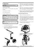
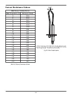
Page 52: ...hould be no resistance Fig 43 Direct Spark Igniter Water Sensor Outdoor Sensor Water Temperature F Resistance ohms 32 32550 41 25340 50 19870 59 15700 68 12490 77 10000 86 8059 95 6535 104 5330 113 43...

Page 53: ...ate drain is inspected and ensure that condensate is being directed to appropriate con densate management system or drain as required by local codes 3 Check that area is free from combustible materi a...

Page 54: ...r 4 Conduct a combustion test at high and low fire Carbon dioxide should be 8 5 to 9 0 at full fire for natural gas and between 9 5 to 10 0 for propane gas Carbon monoxide should be 150 ppm 5 Check va...

Page 55: ...fol low the precautions listed for working with ceramic fibers 4 Spray the coils with clear water making sure to con fine the spray to the area being cleaned DO NOT get the back ceramic wall of the u...

Page 56: ...y however choose to use outside combustion air for one or more of these reasons 1 Installation is in an area containing contaminants listed below which will induce acidic condensation 2 You want to re...

Page 57: ...l horizontally vented gas fueled equipment installed in every dwelling building or structure used in whole or in part for residential purposes including those owned or operated by the Commonwealth and...

Page 58: ...ntamination of combustion air or use of chemical additives to water PARTS REPLACEMENT Under this Warranty Raypak will furnish a replacement for any failed part The failed part must first be returned t...

Page 59: ...____________ Stack Height _______ Low Water Cutoff _______________Test Category _________ sketch vent on reverse side Number of Tanks and Size Qty____ _______Gallons Vent Material __________________ P...

Page 60: ...60 www raypak com Raypak Inc 2151 Eastman Avenue Oxnard CA 93030 805 278 5300 Fax 805 278 5468 Litho in U S A...

Reviews: