CAUTION:
This appliance has provisions to be
connected to more than one supply source. To
reduce the risk of electric shock, disconnect all such
connections before servicing.
CAUTION:
Risk of electric shock: More than one
disconnect switch may be required to de-energize
the equipment before servicing.
Ignition Control Functions
When there is a call for heat, and all safeties are
closed, then the combustion air blower starts to purge
air from the combustion chamber. After the pre-purge,
the igniter is energized. The standard ignition module
will lock-out after failing to light 3 times during a call for
heat. To reset the lock-out, press and release the
RESET
button located on the user interface. The con-
trol will automatically reset after 1 hour. When in
lock-out the control will run the blower through a post-
purge cycle.
The single-try ignition module (part of the CSD-1
option) will attempt to light only one time before lock-
out occurs. To reset the lock-out, press and relase the
RESET
button located on the user interface.
Turning off the power to the heater WILL NOT reset
the single-try ignition module.
High Limit — Manual Reset
The heater is equipped with a fixed setting manual
reset high limit temperature device as standard and it
may have an additional optional adjustable manual
reset high temperature device.
Standard
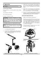
The fixed setting manual reset high limit is built into the
PIM, it utilizes a dual element sensor located on the
outlet (see Fig. 29). To reset a high limit lock-out, press
and release the RESET button located on the user
interface.
Optional
The Optional adjustable setting manual reset high limit
is located behind the front panel. To reset a high limit
lockout, press the reset button on the adjustable man-
ual reset limit as well as the reset button located on the
user interface.
STANDARD
LIMIT SENSOR
OPTIONAL
ADJUSTABLE
SETTING
Fig. 29: High Limit (Manual Reset)
High Limit — Auto Reset (Optional)
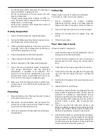
The heater may be equipped with a fixed auto-reset
high limit temperature device and/or an adjustable
auto-reset high limit temperature device. The optional
auto reset high limit is located on the brass outlet
adapter inside the unit, and the adjustable auto-reset
high limit is located inside and behind the front panel.
Fig. 30: High Limit (Auto Reset)
FIXED SETTING
ADJUSTABLE
SETTING
NOTE:
Ignition modules are common for all model
sizes. However, model-specific operating parame-
ters are defined by their respective ID cards.
NOTE:
Adjustable limits must be set higher than the
expected outlet temperature of the unit during nor-
mal operation, to prevent short cycling and nuisance
trips.
35
Summary of Contents for 300A
Page 44: ...WIRING DIAGRAM 44...


