


System Outline
Service Manual 5-7
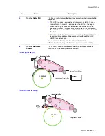
5.1.5 Fuser (Fusing Process)
Toner that has been through the primary and
secondary image transfer processes is fused or fixed
to the paper..
The fuser consists of two heat lamps, two heat
rollers, one thermistor, and two thermostats. The
fuser melts the toner onto the paper using pressure
and heat to complete the printing process.
1) Thermostat (2)
The thermostats are temperature cut-off devices.If the heat lamps or heat rollers overheat, the thermostat turns off
power to the lamps to prevent fire.
2) Thermistor (1)
The thermistor detects the temperature of the heat roller’s surface, and feeds this information to the main
processor. The processor uses this information to control power to the fuser lamps in order to maintain a steady
temperature to the heat rollers.
3) Heat Roller (2)
Halogen lamps are used to heat the heat rollers. The heat rollers have a special Teflon surface which ensures that
any melted toner coming into contact with the heat roller surface does not stick. Paper passes between the two
rollers which evenly heat the paper from both sides to melt the toner and fusing it onto the media.
4) Safety Information -
Warning
Overheat protection
1st level protection: Print engine is stopped if overheat
is condition is detected.
2nd level protection: Software turns off lamp power if
overheat condition is detected.
3rd level protection: Thermostat turns off lamp power if overheat condition is detected.
Protection device
Fuser power is turned off when the duplex cover or the toner cartridge door is open.
The printer keeps the surface temperature of the fuser cover under 80° C, and has a caution label attached inside
the exit cover where it can be easily seen by the user.
Heat Roller
Heat Roller
Heat Lamp
(500W)
Heat Lamp
(300W)
Paper
Spring
Summary of Contents for Phaser 6100
Page 1: ...Service Manual X XEROX P h a s e r C o l o r L a s e r P r i n t e r 6100 ...
Page 2: ......
Page 10: ...vi ...
Page 22: ...Reference Information 2 6 ...
Page 28: ...Specifications 3 6 ...
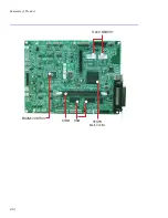
Page 38: ...Summary of Product 4 10 RAM DIMM SPGPm Main Control FLASH MEMORY ENGINE CONTROL ...
Page 44: ...Summary of Product 4 16 ...
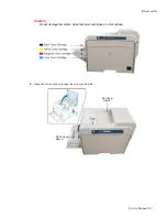
Page 66: ...Disassembly 6 10 3 Remove the toner caps and fit them to the inlets as shown below Toner Cap ...
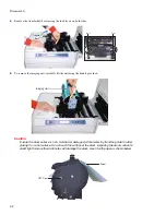
Page 94: ...Disassembly 6 38 6 Disconnect 2 harnesses and remove the laser unit Harness Harness ...
Page 130: ...Maintenance and Diagnostics 7 20 ...
Page 196: ...Parts List 9 42 9 21 Transfer Belt Cam Assembly S18 9 0 8 S8 7 6 5 10 1 2 14 3 12 13 S8 11 4 ...
Page 200: ...Parts List 9 46 ...


