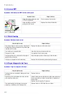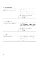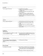
Troubleshooting
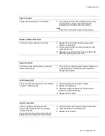
Service Manual 8-23
Page to complex
The layout of the document is too complex
1.
Try printing again after after simplifying and/or erasing
any unnecessary images. If the message recurs
repeatedly, you will need to add more memory.
Note
Note
Note
Xerox does not currently support adding memory
Replace Transfer Roller Soon
The transfer roller is nearing it’s end of life.
1.
Replace the transfer roller when the image quality
becomes unacceptable.
2.
You can select whether this message displays on the
control panel or not.
3.
Remember to reset the transfer roller life at the control
panel after replacing with a new roller.
Ready IP Conflict
IP address confilict with the address of another
device on the network.
1.
This only occurs when the optional network interface card
is connected and an IP address conflict is detected.
Change the IP address.
Install Imaging Unit
This occurs when the imaging unit is not correctly
installed or seated properly.
1.
Verify the imaging unit is properly installed.
2.
Replace the imaging unit.
3.
Check the imaging unit harness to the main board.
■
Reseat or replace if defective.
4.
Replace the main board.
Install Transfer Belt
There is a problem with the transfer belt.
Occurs when the transfer belt is not correctly
installed or locked.
Occurs when the value of the resistor cnnot be
detected due to contamination of the contacts.
1.
Verify the transfer belt is properly installed and locked.
2.
Clean the contacts on the transfer belt.
3.
Replace the transfer belt.
Summary of Contents for Phaser 6100
Page 1: ...Service Manual X XEROX P h a s e r C o l o r L a s e r P r i n t e r 6100 ...
Page 2: ......
Page 10: ...vi ...
Page 22: ...Reference Information 2 6 ...
Page 28: ...Specifications 3 6 ...
Page 38: ...Summary of Product 4 10 RAM DIMM SPGPm Main Control FLASH MEMORY ENGINE CONTROL ...
Page 44: ...Summary of Product 4 16 ...
Page 66: ...Disassembly 6 10 3 Remove the toner caps and fit them to the inlets as shown below Toner Cap ...
Page 94: ...Disassembly 6 38 6 Disconnect 2 harnesses and remove the laser unit Harness Harness ...
Page 130: ...Maintenance and Diagnostics 7 20 ...
Page 196: ...Parts List 9 42 9 21 Transfer Belt Cam Assembly S18 9 0 8 S8 7 6 5 10 1 2 14 3 12 13 S8 11 4 ...
Page 200: ...Parts List 9 46 ...


