


System Outline
5-4
5.1.4 Image Transfer
The toner image formed on the drum and transferred to the transfer belt is called the primary image transfer or T1.
When the final color image has been placed on the transfer belt it is then transferred onto the paper by the transfer
roller, this is called the secondary image transfer or T2.
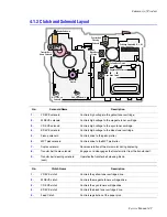
No.
Name
Description
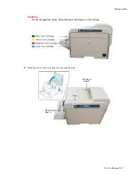
1.
Transfer Belt (T1)
Receives the four color image from the drum in Y, M, C, K order.
2.
Image Transfer Cleaner
After the final image is transferred onto paper by the transfer roller, any
toner left on the belt is removed using this cleaning blade.
3.
PTL Pre-Transfer Lamp
The pre-transfer lamp removes the charge holding the toner on the drum
allowing the toner to be transferred to the belt.
4.
CTD Sensor
This sensor monitors the density of each color toner being placed on the
drum. It is also used to detect a toner cartridge empty state.
The drum surface and toner have different light reflecting characteristics,
the CTD sensor uses this to detect the difference in the amount of toner
present on the drum.
Caution
Be careful not to contaminate the surface of the CTD sensor, this will
cause problems with color reproduction and quality.
Process: The TRC (Tone Reproduction Curve) control process is used
at power on, after waking from sleep mode, after every 100 pages of
printing, and after installing a new toner cartridge or OPC drum to check
the toner density transferred onto the OPC. Small patches of 6.25%,
25%, 37.5%, 50%, 62.5%, 75%, 87.5%, and 100% density for each of the
4 colors are deposited on the OPC drum surface and the CTD is used to
detect how much toner is transferred. Based on an internal calibration
curve the TCR control process adjusts the developer bias voltage to
ensure that optimal toner transfer takes place.
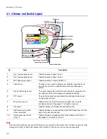
DUPLEX
OPC DRUM
1
2
3
6
4
5
Paper Path
Summary of Contents for Phaser 6100
Page 1: ...Service Manual X XEROX P h a s e r C o l o r L a s e r P r i n t e r 6100 ...
Page 2: ......
Page 10: ...vi ...
Page 22: ...Reference Information 2 6 ...
Page 28: ...Specifications 3 6 ...
Page 38: ...Summary of Product 4 10 RAM DIMM SPGPm Main Control FLASH MEMORY ENGINE CONTROL ...
Page 44: ...Summary of Product 4 16 ...
Page 66: ...Disassembly 6 10 3 Remove the toner caps and fit them to the inlets as shown below Toner Cap ...
Page 94: ...Disassembly 6 38 6 Disconnect 2 harnesses and remove the laser unit Harness Harness ...
Page 130: ...Maintenance and Diagnostics 7 20 ...
Page 196: ...Parts List 9 42 9 21 Transfer Belt Cam Assembly S18 9 0 8 S8 7 6 5 10 1 2 14 3 12 13 S8 11 4 ...
Page 200: ...Parts List 9 46 ...


