background image

69

XAG AUSTRALIA

  Task System

This Icons, and the related information and available options 
are depended on the attached Task System. 

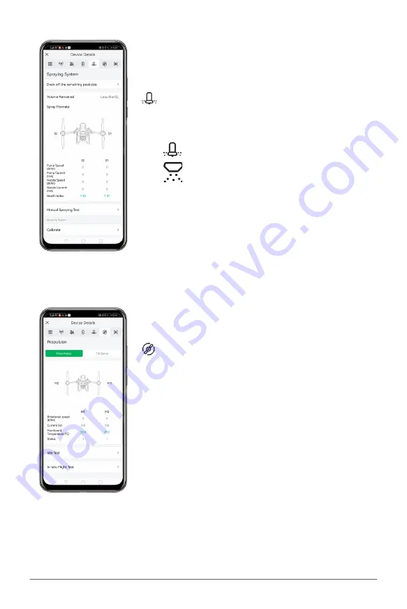
   RevoSpray

   RevoCast

  Propulsion

This Interface displays the information about Propulsion 
System and the options for pilot to conduct Calibration, Ground 
& Flight test to ensure all the motors are operating correctly.

Before Flight operation, it is recommended to ensure

Idle Test: 


Ground Test for Motor

In-Situ Flight Test: 

Testing via Aircraft Taking-off & Landing

Servo Calibration: 

Balancing the Servo  

Summary of Contents for P100 2022

Page 1: ...XAG P100 2022 Pilot s Operating Handbook LNT Mode EN Version AU V1 2...

Page 2: ......

Page 3: ...me These documents are available online on the XAG Product page at https www xagaustralia com au productsupport EXCEPT AS EXPRESSLY PROVIDED IN XAG AFTERSALES SERVICE POLICIES AVAILABLE AT https www x...

Page 4: ...ITS GOODWILL OR ANY OTHER INTANGIBLE LOSS ARISING OUT OF OR RELATING TO YOUR ACCESS TO OR USE OF OR YOUR INABILITY TO ACCESS OR USE THE PRODUCT PRODUCT ACCESSORIES OR ANY MATERIALS FLIGHT ENVIRONMENT...

Page 5: ...pesticides depends on chemical density spray rate spray distance flight speed wind speed wind direction temperature humidity and more Consider all factors and applicable laws or regulations when usin...

Page 6: ...recommended to ensure flight safety Maintain complete control of the aircraft at all times Obstacle avoidance is disabled in certain situations and operating environments Effectiveness of the Obstacl...

Page 7: ...t covered by the Product warranty Some of the scenarios that may decrease the Ingress Protection include but are not limited to the following There is a flight incident collision causing the sealing t...

Page 8: ...t personal privacy Don t record or photograph people without their consent this may breach other laws You must not fly your drone over or near an area affecting public safety or where emergency operat...

Page 9: ...Wiring Guide 19 Status Indicator 21 XAG RevoSpray 2 24 Product Profile 24 Overview XAG RevoSpray 2 24 Installation Guide 25 Assembling the XAG RevoSpray 2 25 Connect Cables 26 Connect Liquid tube 26...

Page 10: ...or Battery 41 Status Indicator Smart Device 41 Status Indicator Device 42 Status Indicator Control Mode 42 Status Indicator Terminal 42 Status Indicator RTK 42 Using the Remote Controller 43 Inserting...

Page 11: ...RTK Module Console 62 XAG One APP 63 Download XAG One APP 63 APP Operation View 64 APP Aircraft Module 67 Preparing the Equipment 71 Installing the Battery 71 Turning the Aircraft ON OFF 71 Unfolding...

Page 12: ...g via Rover Mode 107 Manage Fields 110 Edit Fields 111 Route Pre Planning 112 Aerial Flights 113 Safety Guidelines 113 Pre Flight Checklist 114 Aerial Spraying 115 Emergency Control 119 After Flight M...

Page 13: ...quipped with SuperX4 Pro Intelligent Flight Control System which perfectly combines robust AI algorithms and high performance power assembly The highly integrated SuperX4 Pro Intelligent Flight Contro...

Page 14: ...STRALIA 14 Please check that the following items are all present when unpacking the box Should there be any item missing please contact your dealer List of Items P100 Airframe 1 Tool Kit 1 Control Sti...

Page 15: ...ing Gear Mounting Bracket 03 4D Imaging Radar 10 Landing Gear 04 UPS Battery Backup 11 Peristaltic Pump 05 Airframe Hasp 12 Liquid Tank 06 ESC Electronic Speed Controller 13 Arm 07 Motor 14 Nozzle Ove...

Page 16: ...Cap 21 Central Cabin 17 2 4GHz Antenna 22 Arm Position Number 18 Airframe Nameplate 23 Battery Compartment 19 Status Indicator Fig 2 Airframe Module Arms Notes There are corresponding laser engraving...

Page 17: ...Nozzle Signal Cable from the Nozzle Extension Rods 03 Turn the quick release knob counter clockwise to release and remove the Nozzle Extension Rods 04 Detach the Nozzle Extension Rods and insert the...

Page 18: ...sure the Nozzle Extension Rod is properly secured 03 Insert the Nozzle signal Cable in and through the Nozzle Extension Rods 04 Connect the Liquid Tube and secure the connected liquid tube with cable...

Page 19: ...19 XAG AUSTRALIA Wiring Guide...

Page 20: ...XAG AUSTRALIA 20...

Page 21: ...no output from the board Red Green Alternate Flashing Initializing Configurating Rapid Flash Red Green Alternate Updating firmware Status Indicator SuperX4 FC Status Indicator FC Indicator 4G Descript...

Page 22: ...Manual mode Single Flashing Purple Initialization failed or preheating Flashing Red Fast Sensor error Flashing Blue Fast Propulsion system error Flashing Purple Fast Underlying controller formatting i...

Page 23: ...er formatting incorrect parameters Double Flashing Red Flight in safe mode Double Flashing Green Manual GPS mode good GPS signal Flashing Red Green Weak GPS signal Triple Flashing Red Low voltage Trip...

Page 24: ...attery operation can be flexibly chosen in different scenarios with a 10 meter Spray swath and 40 kg effective payload the optimal efficiency for land blocks of different sizes will be achieved The ne...

Page 25: ...hrough the spacing between the Airframe and the RevoSpray System 02 Align the Airframe s limit hole to the boss alignment of the RevoSpray system then gently places the Airframe onto the RevoSpray sys...

Page 26: ...Cable 05 Affix and secure the cable to the cable holder above the Peristaltic pump RevoSpray Cable Mount Cable Connect Liquid tube 06 Connect the two liquid tubes to the connectors of the Peristaltic...

Page 27: ...27 XAG AUSTRALIA Unfolding Nozzle Extension Rods 07 Gently lift the Nozzle Extension Rod inwards and then rotate it outward 01 02...

Page 28: ...o the innovative new intelligent spiral feeder the screw conveyor can be changed according to the size of granules and the inline opposed centrifugal spreading discs greatly improves the wind resistan...

Page 29: ...05 06 07 08 09 10 11 12 01 Doppler sensor 06 Hook 02 Boss alignment 07 Name Plate 03 Material container cover 08 Cable Holden 04 Landing Skid 09 Material container 05 Quick Assembly Unit Hasp 10 Spre...

Page 30: ...the aircraft after each operation and before swapping the Payload System 01 Refill the Liquid Tank with soap water or soap powder water and engage all nozzles to drain and clean out remaining residues...

Page 31: ...he Airframe s limit hole to the boss alignment of the RevoCast system then gently places the Airframe onto the RevoSpray system Boss Slot 02 Lock and secure the 2 Airframe Hasps to the RevoCast System...

Page 32: ...XAG AUSTRALIA 32 Connect Cables 04 Connecting the Mounting cable to the RevoSpray Cable 05 Affix and secure the cable to the cable holder above the Peristaltic pump RevoCast Cable Mount Cable...

Page 33: ...llowing items are present when unpacking the box Should there be any item missing please contact your seller immediately Antenna 2 Stand 1 Local Network Terminal LNT 1 Power Adapter 1 List of Items Lo...

Page 34: ...XAG AUSTRALIA 34 Antenna Stand Indicator Power Button Power Port Reset Button Overview Local Network Terminal...

Page 35: ...ssemble the antennas 02 Connect the Terminal of the Power Adapter to the Battery Terminal 03 Connect the Output plug of the Power Adapter to the LNT Power port 04 Place the LNT on the stand 01 02 03 0...

Page 36: ...Power button on the LNT for at least 1 second and release after the first indicator turns on The device may take up to 10 minutes for the initialization the initialization is completed approximately...

Page 37: ...WLAN On Wi Fi networking function normal WLAN Flashing Wi Fi network is busy WLAN Off Wi Fi network error WAN On Access to WAN for data synchronization WAN Flashing Wi Fi network is busy WAN Off Wi F...

Page 38: ...er Remote Controller Please carefully check if the product contains all the items listed below and your dealer if there are any missing items ControlStick Body 1 Power Adapter 1 USB To Type C Cable 1...

Page 39: ...ad Spray Spread Button Spray Spread Speed Speed Broadcast Button Speed Button A Smart Mode Button Button B 17 18 19 20 22 21 23 24 25 Bottom View 26 Power Button 27 Nano SIM Slot 28 29 Altitude Altitu...

Page 40: ...ode Add Point 15 Smart Mode Button Long Press to Enter Exit mapping Mode 16 Button B Mapping Mode Undo previous Added Point 17 Yaw Control Left Rotate Device CCW Counter Clockwise 18 Yaw Control Right...

Page 41: ...59 Solid Green 60 100 When ACS2G is ON the battery level indicator display the current battery level ACS2G Remote Controller will broadcast Low Battery when the remaining power is less than 5 and will...

Page 42: ...r OFF Device Not Connected Local Network Terminal Description Solid Green LNT Connected OFF Not Connected RTK Description Green Flashing Rover Mode Float Solid Green Rover Mode RTK Solid Red Rover Mod...

Page 43: ...troller is turn OFF 02 Gently unplug the rubber plug on the left of the Remote Controller 03 Insert the nano SIM card in as the direction shown in the figure 04 Close and Secure the Rubber Plug ACS2 u...

Page 44: ...troller Power Port The Battery Level and the mode of charging is indicated by the Battery Level Indicator Status Indicator Battery Description Quick Flash Quick Charging Mode Slow Flash Standard Charg...

Page 45: ...cators flash simultaneously 2 Release and then Press and Hold the Power Button again until a Broadcast is heard from the Remote Controller TURN OFF 1 Press and Hold the Power Button until all the indi...

Page 46: ...ound IMPORTANT TAKE OFF Press and Hold both Altitude Control Buttons for 3 Seconds the RPA will automatically take off and hover at 2 5 meters LAND Press and Hold both Altitude Control Buttons to comm...

Page 47: ...e Press the Speed Button to decrease the Flight Speed by 0 5m s The Maximum Flight speed of the RPA with Obstacle detection is 0 5m 6 0m s IMPORTANT Move the RPA Forward Move the RPA Backward Move the...

Page 48: ...y Spread Button to decrease the Dosage Rate of Spray Spread Broadcast Press the Terrain Button Once to broadcast the current Mode GPS Height Terrain Follow Switch Mode Quick press the Terrain Button T...

Page 49: ...Operation Task Attaching Slide insert the ACS2 RTK Module onto the top of the ACS2G Remote Controller When the ACS2G RTK Module is inserted the ACS2G Remote Controller will broadcast Module Inserted...

Page 50: ...y Handle Indicator Panel Battery Clip Air Outlet Air Inlet Max Water Level Min Water Level Solid Normal Slow Flash Overcooled Fast Flash Overheated Double Flash Error Power Button Structure Battery Le...

Page 51: ...otherwise the power ports may be damaged X DO NOT use or store battery near heat sources such as a furnace heater and within a vehicle during hot days X DO NOT use Batteries with abnormal conditions...

Page 52: ...Level on both batteries required Battery Status Indicator Status Description Red Solid Normal Normal Red Quick Flash Too HOT Temperature is too HOT Charging Discharging temporary Disable Red Slow Flas...

Page 53: ...ttery in Water or Battery will be damage X DO NOT use Corrosive liquids for heat Dissipation or Battery will be damage X DO NOT exceed 60 minutes for heat Dissipation or Battery will be damage X DO NO...

Page 54: ...XAG AUSTRALIA 54 Charging with CM12500P Battery Charger Charging with GC4000 Auto SuperCharger Station Charging with GC4000 Auto SuperCharger Station with Charging Water Tank...

Page 55: ...mbient environment of 10 C to 30 C ENSURE the Batteries are recharge every 90 days to maintain battery health X DO NOT Store Batteries with less than 30 Power X DO NOT store Batteries for an extended...

Page 56: ...put indicator Status Description Solid Green Normal Normal Flashing Green Not Grounded Risk Exist Solid Red Error Protection Triggered Output OFF Flashing Red Overheated Protection Triggered Output OF...

Page 57: ...alcohol or other combustible liquids X DO NOT disconnect the AC cable or the Charging cable while the Charger is in use Remove batteries after charging is completed X DO NOT use this product under di...

Page 58: ...ems GNSS XRTK4 Mobile Station GNSS XRTK4 Mobile Station Balance Plate 1 Tripod 1 B4100 Battery Extension Rod 1 GNSS XRTK4 Module 1 Toolbox 1 Power Supply Cable 1 GNSS RTK Module GNSS RTK Battery GNSS...

Page 59: ...tation 2 3 4 1 5 6 GNSS RTK Module B4100 Battery Extension Rod Balance Plate Tripod Battery Extension Rod Console Antenna The XRTK4 Mobile Station is comprised of the GNSS RTK Module B4100 Battery Ext...

Page 60: ...o low recharge before use 02 Connect the battery to a device then press the Power button once for at least 1 second until all the indicator lights flashes then press and hold the power button again fo...

Page 61: ...ll battery level indicators will be on Battery Status Indicator LED Status Description Red Solid Normal Normal Red Quick Flash Too HOT Temperature is too HOT Charging Discharging temporary Disable Red...

Page 62: ...rs in different colours Checking Operation Status Operation Status Indicator Status Red Light ON Normal Red Slow Flash WLAN initializing about 30 seconds Red Quick Flash Voltage is low 12 5V Immediate...

Page 63: ...Controller RTK Station It enables the Users to configure various settings planning a field and operating the aircraft autonomous following the pre planned flight routes and configuration and manually...

Page 64: ...XAG AUSTRALIA 64 APP Operation View 13 14 15 16 17 18 19 12 11 08 09 10 07 01 02 03 04 05 06...

Page 65: ...tonomous Operation 05 Battery Shows the remaining Battery Voltage 06 Liquid Shows the remaining volume of the RPA s Liquid Container 07 Hover Continue Hover Command the RPA to Hover Continue Command t...

Page 66: ...Map Map data based on previous surveyed and processed data Field Field data based on previous planned field 14 Position Aircraft Tap to centre the map around the selected Aircraft 15 Position Smart De...

Page 67: ...t with Team Members or Lease to other pilots Edit the Unique name for the Aircraft Update Module firmware and remove device from this account Communication This interface displays the basic informatio...

Page 68: ...Delay 10 seconds Aircraft is connected to an RTK Base Station Battery This interface contains information related to the battery on the aircraft battery model battery cycle remaining power are all di...

Page 69: ...his Interface displays the information about Propulsion System and the options for pilot to conduct Calibration Ground Flight test to ensure all the motors are operating correctly Before Flight operat...

Page 70: ...he information and current settings of the sensor module available on the Aircraft primarily with Terrain Radar Obstacle Avoidance and PSL Camera This interface would also allow the pilot to Turn ON O...

Page 71: ...second until all the indicator lights flashes then press and hold the power button again for approximately 1 second until you hear a beep from the battery 03 Please be patient and wait until the Aircr...

Page 72: ...thers and damage to your Products and or other objects in the vicinity Check and ensure the correct corresponding Propeller is attached the model of the propeller can be found between the Propeller bl...

Page 73: ...rt Device and input the following Web Address http www iotlogin com 04 Enter the password and login to the Module to edit Settings Default LNT Admin Password 20070401 01 Power ON the Local Network Ter...

Page 74: ...ection Status of the External Wi Fi is indicated by the WAN Indicators 3rd Indicator Router Setup Administrator Settings for Local Network Terminal Default LNT Wi Fi Network XAG XXXX XXXX is the last...

Page 75: ...urn ON the RTK Module Open XAG One APP 02 Tap on Me to access Account Menu 03 Tap on Device PREREQUISITE IMPORTANT LNT Local Network Terminal must be connected to an external internet available networ...

Page 76: ...Press and hold F1 on the RTK Module Console for at least 3 seconds and release after hearing a beep This indicate that the RTK Module is ready to bind 07 Tap on Settings to bring up the Available Wi F...

Page 77: ...work Name Password for the LNT Local Network Terminal then save the settings via Confirm Default LNT Wi Fi Network XAG XXXX Default LNT Password 20070401 Check ensure the entered LNT Network Name Pass...

Page 78: ...the Main Page of the APP Tap on the and select Add a Device 13 Press and hold F3 on the RTK Module Console for at least 3 seconds and release after hearing a beep All the Status Indicator will flashe...

Page 79: ...STRALIA 16 If the APP display the Device has been added successfully 17 Return to the Device Menu and check if the Device is displayed in your list of Device 18 Please restart APP once the binding is...

Page 80: ...nected before Opening APP 01 Turn ON the Remote Controller Open XAG One APP 02 Tap on Me to access Account Menu 03 Tap on Device PREREQUISITE IMPORTANT LNT Local Network Terminal must be connected to...

Page 81: ...en Tap on for Device Binding 05 Tap on Remote Controller to start Binding 06 Tap on Settings to bring up the Available Wi Fi List 07 Select the corresponding ACS2 Wi Fi Default ACS2G Wi Fi Network ACS...

Page 82: ...me Password for the LNT Local Network Terminal then save the settings via Confirm Default LNT Wi Fi Network XAG XXXX Default LNT Password 20070401 Check ensure the entered LNT Network Name Password is...

Page 83: ...Main Page of the APP Tap on the and select Add a Device 12 Press and hold the Power Button of the Remote Controller for 6 10 seconds and release after all indicators are flashing Red This indicates th...

Page 84: ...ALIA 84 15 If the APP display the Device has been added successfully 16 Return to the Device Menu and check if the Device is displayed in your list of Device 17 Please restart APP once the binding is...

Page 85: ...before logging into Open APP PREREQUISITE LNT Local Network Terminal must be connected to an external internet available network indicated by the WAN indicator on the LNT Device Binding can only be a...

Page 86: ...r 2 seconds then release it Repeat the press hold once more for 2 seconds then release it again The Wireless Communication indicator 3rd Indicator will start flashing orange indicating the Aircraft is...

Page 87: ...Tap on I m Connected to access Equipment Network Settings 10 Return to the APP and Tap on I m Connected to access Equipment Network Settings 11 Enter the LNT Wi Fi Network Name Password for the LNT L...

Page 88: ...LNT Wi Fi Check Ensure the LNT Wi Fi Network is connected 12 Return to the Main Page of the APP Tap on the and select Add a Device 13 Add the Device by Scanning the QR Code on the Device or Enter the...

Page 89: ...89 XAG AUSTRALIA 16 Return to the Device menu and check if the Device is displayed in your list of Devices 17 Please restart the APP once the binding is completed...

Page 90: ...obile Station Select solid and flat ground with open space above There should be no obstacles over the elevation angle of 15 for continuous tracking and observation of the satellite and high quality s...

Page 91: ...shown 04 Tighten the fixing bolts on the Tripod to firmly secure the Balance plate 05 Place the Rover assembled in Step 2 from top into the spacing hole and close the buckle to complete the assembly...

Page 92: ...ill refresh and display as FIX Normal 08 RTK Mobile Station is now ready for USE CHECK Check Ensure the Positioning Status of the RTK Module Console is in FIX Mode Triple Flashes Check Ensure the Posi...

Page 93: ...Connected Device binding of XRTK4 Mobile Station had been setup ACS2 RTK Module had been attached PREREQUISITE IMPORTANT Please be patient the devices may take up to several minutes before coming ONLI...

Page 94: ...e Menu Tap on Remote Controller for Device details 06 Tap on Set Base Station for Base Station Settings 07 The APP will automatically detect and display the available base station nearby 08 Select the...

Page 95: ...yed 10 Tab on to return to Remote Controller Device details and ensure the following RTK Positioning is now RTK Active Set Base Station is now Connected to a Mobile Station Displaying Station ID such...

Page 96: ...Aircraft for Device Detail 03 Tap on the for Positioning System then taps on RTK Base Station 1 2 3 LNT Local Network Terminal Wi Fi Network had been set up Connected Device binding of GNSS XRTK4 Mobi...

Page 97: ...s for nearby station based on the positioning of the Aircraft If the Aircraft is placed indoor or area where it can t be positioned the APP may not be able to search for Nearby Station Warning 07 Retu...

Page 98: ...Aircraft for Device Detail 03 On the Universal Information Tab Tap on Pair with ControlStick 1 2 3 LNT Local Network Terminal Wi Fi Network had been set up Connected Device binding of ACS2G Remote Co...

Page 99: ...corresponding Remote Controller and then tap on Pair for Pairing 05 When the Pairing is completed it will display Pairing Successful 06 Return to the Device Menu and check the status of Bind Remote C...

Page 100: ...Set as operation Device 1 2 3 Aircraft are required to be set as operation devices before they can be used for Aerial Survey Spraying or Spreading LNT Local Network Terminal Wi Fi Network had been set...

Page 101: ...101 XAG AUSTRALIA 04 The corresponding aircraft is now set as an operation device and is available for operation Notes Maximum of 2 Aircraft can be set and used for operation simultaneously 4...

Page 102: ...hat had imported the data Internet Access to Cloud for Data Retrieval Using the same XAG Account PREREQUISITE This section is primarily for previous XAG Pilots to access Fields that had been previousl...

Page 103: ...ll be displayed 05 Alternatively the user may choose to search for the fields as well 06 Select 1 or Several fields then confirm to start importing the field to this Smart Device 07 After the field is...

Page 104: ...h the field or pilots who have surveyed the area for an HD Map Satellite map accuracy varies and is not recommended for a new or inexperienced pilot unfamiliar with the field or the Aircraft The pilot...

Page 105: ...on one of these to expand the menu for alternate options 06 Tap on the desired location on the map to Add points 07 Alternatively the User can use the crosshair to add boundary obstacles and Restricte...

Page 106: ...XAG AUSTRALIA 106 10 The field has now been created 11 Tap on to review the List of Field HD Map Device The field is now available for Route Planning...

Page 107: ...Remote Controller had been set up Connected Devices are ON and displaying as Online in Device Menu ACS2 RTK Module had been attached Online ACS2G XRTK Mobile Station Number of Satellites Connected 16...

Page 108: ...P Press on APP Adding Point via Remote Controller Press Button A on Remote Controller Removing Point via Remote Controller Press Button B on Remote Controller Field Boundary Field Boundary are individ...

Page 109: ...AG AUSTRALIA 07 Enter Insert Field Information then Tap Complete to Save 08 The field has now been created 09 Tap on to review the List of Field HD Map Device the field is now available for Route Plan...

Page 110: ...ponding fields for additional options 03 Additional options include Aerial Flight Aerial Survey Manage fields Share Field and more 04 Proceed to Manage Fields to edit or pre plan the fields 05 At the...

Page 111: ...e Points Tap on the points then select Delete Point Restricted Zone Add Points Tap once between the segments and drag the to add Points Move Points Drag the points to the appropriate location Delete P...

Page 112: ...tom Route Custom Route based on the points that the user had added Parameters Route Direction The Direction of each Flight Route Route Spacing The Spacing Distance between each Flight Route Boundary S...

Page 113: ...3m s 6 at 5m s 3 at 7m s RTH will not work if there is a weak or no GNSS Signal Tall objects may adversely affect RTH Therefore it is important to set an appropriate failsafe altitude before each flig...

Page 114: ...Check ensure Firmware APP is up to date 06 Check and ensure there are sufficient battery for the operation Including Aircraft Batteries LNT Remote Controller and RTK Station Battery 07 Check and ensu...

Page 115: ...RTK Remote Controller and Aircraft Completed Setting Aircraft as Operation Device Completed Pre Flight Checklist Completed Field Planning PREREQUISITE 01 Open XAG One APP and tap on the Operation 02...

Page 116: ...l assigned the aircraft for the operation of this field Spray Settings Route Settings is now available for setting Review adjust the settings Refer to Page 117 118 for Spray Settings Route Settings th...

Page 117: ...Adopt Safe Point Planning Enabled This function will allow Pilots to add Guide Point to guide the flight route of the RPA from Take off point to the Task Area Disabled Disabling this function will ena...

Page 118: ...rrain Terrain Following Settings Obstacle Avoidance Dynamic Radar Settings for Obstacles Avoidance Automatic route optimization Break point is the location where the autonomous task was interrupted by...

Page 119: ...mergency Control via ACS2G Remote Controller Motion Control Hover Switch Mode Hover Press the Hover Button to command the RPA to Hover Switch Mode Press and Hold the Hover Button to switch Mode The Re...

Page 120: ...er water and engage all nozzles to drain and clean out remaining residues within the spray system 02 Refill the Liquid Tank with clean water and engage all nozzles to drain and clean out the remaining...

Page 121: ...raft the APP will display the selected Aircraft Name at the Aircraft status Bar Switch Control IMPORTANT Operation with Multiple Aircraft Inspect and ensure the Take off and Landing Location must be c...

Page 122: ...or review Personal Operation Records Personal Operation Records displays the total statistics of this user account Total Operation Area Total Operation Time Total Operation Field Device Operation Reco...

Page 123: ...of all components are firmly secured and there are no signs of oxidation 05 Check and ensure the equipment power socket and battery socket are clean and dry and the sockets are not damaged or deformed...

Page 124: ...n the Propeller Motor 01 Remove the Propeller and Motor housing then clean the Motor with a Compressed Air Duster 02 Rotate the Motor to check the motor bearing for any abnormality vibration or abnorm...

Page 125: ...losion 06 DO NOT use the battery if the battery is leaking bulged deformed or damaged in appearance 07 DO NOT disassemble the Battery without XAG s authorization 08 DO NOT insert or remove the battery...

Page 126: ...and Spray Tubes are not shrivelled deformed or lost its elasticity Replace tubing if any of the above symptoms are found Peristaltic Pump 01 Disassemble the Peristaltic pump and ensure the peristalti...

Page 127: ...ion of foreign objects attaching entangling or material jamming Cleaning 01 Disconnect the Spreader signal cable 02 Unfasten the Hasp securing the Quick release Unit and extract the Quick release Unit...

Page 128: ...he wear and tear on a single side exceed 2mm Original diameter 79mm 02 Check and ensure the Cross Slot of the Screw conveyor are kept clean and free of foreign objects 04 Open both container covers an...

Page 129: ...tainer matching the Cross Axle of the RevoCast to the Cross Slot of the Quick release Unit 05 When the Quick release Unit is properly inserted close and lock the Hasp and ensure the Quick release Unit...

Page 130: ...onment within the temperature range of 10 C to 30 C Equipment should NOT be stored in a moist environment or where there is water leakage Moist environment Water leakage In addition to smart batteries...

Page 131: ...uids and residues must be drained from the aircraft prior to transportation liquids or residues remaining within the spray system during transportation may cause damage to the critical module Batterie...

Page 132: ...Then firmly secure the aircraft with the airframe mounting brackets Do not drive fatigued and the equipment should be kept and stored away from the occupant Maintain air circulation and avoid pesticid...

Page 133: ...133 XAG AUSTRALIA Technical Specifications Product Model 3WWDZ 40AH Flight Control System SuperX4 Pro IP Rating IPX7 Arm Material Glass Fibre Carbon Fibre Composite P100 Agricultural RPA...

Page 134: ...ccuracy Range With Strong GNSS Signal RTK Enabled 10cm Horizontal 10cm Vertical RTK Disabled 0 6m Horizontal 0 3m Vertical RTK GNSS Operating Frequency GPS L1 L2 GLONASS L1 L2 BDS B1 B2 Galileo E1 E5b...

Page 135: ...Continuous 200A Max Operating Voltage 56 4V ESCs Model P4718 Diameter x Pitch 47 x 18 inch Weight 280g per Blade Gross Weight 760g Foldable Propellers Propulsion System PSL Camera Model RD24412 Dimen...

Page 136: ...5m Relative Speed 8m s 4D Imaging Radar 1 Obstacle Sensor Avoidance System Model TR24S100 Voltage 12V Power 1 5W Sensing Mode Millimeter wave Operating Frequency 24GHz Altitude detection range 0 5 100...

Page 137: ...0RPM 16000RPM Spray Swath 5m 10m Droplet Size 60 m 500 m Model M4TANP40A Material PE Volume 40L Dimension 947 5mm x 734 5mm x 472 mm Sensor Liquid Level Sensor Liquid Tank Nozzle Quantity 2 Voltage 50...

Page 138: ...mension 983mm x 873mm x 573mm Net Weight 13 00Kg Rated Capacity 60L Rated Load 40Kg Optimal Operating Temperature 0 C to 40 C Storage Temperature 0 C to 40 C IP Rating IP65 Applicable granule Size 1 6...

Page 139: ...Communication Protocol Wi Fi Operating Frequency 2400 2483 5 MHz Antenna TNC Port 2dBi Warranty Details 12 Months Dimensions 101mm x 86mm x 37mm Weight Approx 335g Power Input DC 40 54V B13960S Batte...

Page 140: ...ture 20 C to 55 C Storage Temperature 20 C to 20 C 1 Month 20 C to 45 C 1 3 Months 20 C to 55 C 3 12 Months Max Transmission Distance Unobstructed free of interference 800 Meters Charging Voltage Curr...

Page 141: ...nergy 962 Wh Rated Output 48 1V 120A Operating Temperature 10 C to 45 C Charging Temperature 10 C to 40 C Storage Temperature 10 C to 30 C IP Rating IP65 Compatible Aircraft XAG V40 2021 XAG P40 2021...

Page 142: ...rox 9 0 kg Operating Temperature 10 C to 45 C Storage Temperature 20 C to 55 C Cooling Mode Outer Air Cooling Operating Altitude 3000m Input AC 90 165V 50 60Hz 23A Max AC 180 260V 50 60Hz 23A Max Outp...

Page 143: ...C to 60 C Storage Temperature 20 C to 60 C Relative Humidity 100 condensation Warranty Details 12 Months GNSS Performance Specifications Compatible motherboard K726 GNSS Frequency BDS GPS GLONASS Gali...

Page 144: ...735 5 835GHz Channel spacing 20 MHz Frequency error frequency stability 10 ppm Communication mode Full duplex Communication protocol Transparent Forward error correction FEC Data rate 6Mbps Modulatio...

Page 145: ...ustrations photos methods processes etc belongs to XAG Australia and is protected by copyright law No individual or organization may imitate extract translate distribute or reproduce or quote all the...

Reviews: