X-pole X-Stage Instruction Manual Download Page 5

5

®

LEADERS IN POLE & AERIAL FITNESS

Copyright© Vertical Leisure Ltd. 2020                         Version 3.0 

All rights reserved. 

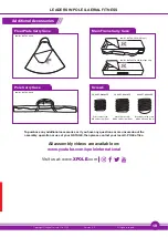
Release Velcro straps

Bag zip

Metal Support Sub-Chassis

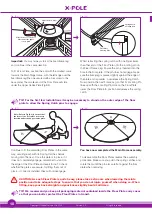
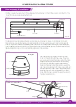
Contents - Carry Case

Start by unzipping the Main Frame Carry Case that 
contains the Main Stage Frame. This is secured with 
Velcro straps inside the carry case on a metal support 
sub-chassis. This carry case also incorporates the 
Sub-Chassis, Handle Bar, Wheels, Side Skirts (X-Stage 
only), along with the hex screws and hex keys to 
secure them.

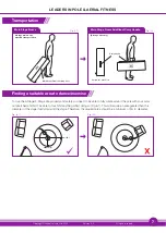
First, remove the Velcro straps securing the Main Stage 
Frame to the Sub-Chassis. Stand with your feet either 
side of the Carry Case, bending your knees slightly and 
keeping your back straight. Position your hands either 
side of the Main Stage Frame as shown and carefully lift 
it and slide out of the Main Frame Carry Case, placing it 
to either the left or right side of the Carry Case for now.

Fig. (3.1)

Fig. (3.2)

Velcro straps

(undone)

Velcro straps

X-Stage Main Frame

CAUTION: The Main Stage Frame is the heaviest single component of the X-Stage/X-Stage Lite, 
so care must be taken not to injure yourself when removing or handling. Please ensure your 
knees are slightly bent and your back is straight when lifting.

TIP: Note how the velcro straps attach and which way round the Main Stage Frame is positioned 
for when you eventually come to pack this away. Take a photo for reference. Putting the Main 
Stage Frame back into its Carry Case and securing it to the Sub-Chassis is the reverse of the 
removal procedure.

Summary of Contents for X-Stage

Page 1: ...Copyright Vertical Leisure Ltd 2020 Version 3 0 All rights reserved Instruction Manual Please Read Fully Before Assembly www XPOLE com...

Page 2: ...n VERTICAL LEISURE LTD X POLE INTERNATIONAL X POLE US INC X POLE CHINA THEIR DISTRIBUTORS SALES PERSONS OR ANY OTHER PERSONS OR ASSOCIATED COMPANIES CANNOT BE HELD RESPONSIBLE FOR ANY DAMAGE TO PROPER...

Page 3: ...use your X STAGE X STAGE LITE you review some online videos to learn the basic moves Never try moves beyond your ability without an instructor If at any time whilst using your pole you feel uncomfort...

Page 4: ...Pole Bearing Unit found under foam pad X Joint 250mm 9 8 B Pole Main Frame Carry Case Fixed Wheels x2 Main Stage Lite Frame 4mm 5mm 6mm Hex Keys Main Stage Frame Main Frame Carry Case Side Skirts x 3...

Page 5: ...ghtly and keeping your back straight Position your hands either side of the Main Stage Frame as shown and carefully lift it and slide out of the Main Frame Carry Case placing it to either the left or...

Page 6: ...per wheel using the 4mm hex key The wheel assemblies have elongated slots in them to allow some movement on the sub chassis frame Position both wheels equally before tightening the hex screws TIP Eas...

Page 7: ...table area to dance exercise To use the X Stage X Stage Lite properly and safely you need to be able to fully rotate around the pole with your arms outstretched and NOT be able to touch hit anything w...

Page 8: ...to the A Pole as this is the depth of the protruding X Joint Therefore a Standard Format X Stage or X Stage Lite will require an overall ceiling height of 3 2m 10 5 or higher If the ceiling height is...

Page 9: ...ch arm should be flat against the plate Fig 9 1 Pull the end of the arm upwards to a vertical position and the catch pin will automatically pop out of the floor plate Each spring catch is spring loade...

Page 10: ...catch Fig 9 3 Fig 9 4 TIP For the first few installations it may be necessary to stand on the outer edge of the floor plate to allow the Spring Catch pins to engage Continue to fit the remaining Floor...

Page 11: ...sitioning the bearing unit in the main frame Fig 10 1 The Pole is made of four parts the A Pole a Bearing Unit that attaches to it the B Pole and an X Joint Fig 10 1 The A and B poles are connected us...

Page 12: ...pole tube Next look inside the Bearing Carrier Ring on the stage top plate and you will see a pin sticking out Look at the Bearing unit on the pole and you will see a slot The pin on the Bearing carr...

Page 13: ...then re tighten all three firmly Replacement screws can be purchased from your local X Pole agent A Pole Bearing Unit Static Spin Screw must be in static mode to remove pole X 5mm Hex Key Fig 11 8 Fig...

Page 14: ...and locks the pole tubes together The joint expansion is done by inserting the hex key through holes in the pole tubes into the hex screws and turning the key clockwise The markings on the tube show t...

Page 15: ...locking screw on the X Joint aligns with the hex key hole in the pole tube otherwise you will not be able to insert the hex key DO NOT TIGHTEN EXPAND NOW Fig 13 1 Fig 13 2 Next take the B Pole and sli...

Page 16: ...r all six feet Apply pressure to the pole in several directions to see whether there is any movement if the stage rises on one side screw the wheel further Once there is minimum movement and the entir...

Page 17: ...per pg 9 10 and now your stage is ready to be used Fig 15 5 5mm Hex Key X Static Spin Screw Bearing Carrier Bearing Cone A Pole Static Spin Static Spin Screw Static Spin Screw X Mark Static Spin mode...

Page 18: ...his will damage the rubber feet DO NOT remove loosen the m8 pole retaining screws when dismantling the pole DO NOT try and remove the pole when in spinning mode damage will occur DO NOT use the X STAG...

Page 19: ...ease contact your local X POLE office All assembly videos are available on www youtube com xpoleinternational Floor Plate Carry Case Main Frame Carry Case Pole Carry Case Screws Additional Accessories...

Page 20: ...sed by A Conditions malfunctions or damage not resulting from defects in material or workmanship B Conditions malfunctions or damage resulting from 1 normal wear and tear improper installation imprope...

Reviews: