


Copyright© Vertical Leisure Ltd. 2020 Version 3.0
All rights reserved.
®
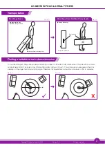
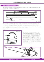
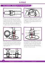
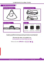
LEADERS IN POLE & AERIAL FITNESS
This product has been manufactured and tested to the highest quality standards by X-POLE. This Limited Warranty offered by X-POLE
covers defects in material or workmanship in new X-POLE products for a period of 6 months
.
This warranty extends to the original purchaser only and is non-transferable. Only consumers purchasing X-POLE products from authorised X-POLE
retailers or resellers or through the X-POLE website may obtain coverage under our limited warranties.
What is covered?
X-POLE warrants this product against defects in material or workmanship as follows:
X-POLE, at its own discretion, will replace at no charge, for parts only, replace any product or part of the product that proves defective because of
improper workmanship and/or material, under normal installation, use, service and maintenance. If X-POLE is unable to provide a replacement and repair
is not practical or cannot be made in a timely fashion, X-POLE may elect to refund the purchase price in exchange for the return of the product.
How Long Does The Coverage Last?
Our warranty periods are 6 MONTHS from the documented date of purchase, depending on the type of product and where it was purchased. This does
not affect your statutory rights.
What Our Warranty Does Not Cover?
Our warranties do not cover any problem that is caused by:
A.
Conditions, malfunctions or damage not resulting from defects in material or workmanship.
B.
Conditions, malfunctions or damage resulting from (1) normal wear and tear, improper installation, improper maintenance, misuse, abuse, negligence,
accident or alteration.
C.
Accessories, connected materials and products, or related products not manufactured by X-POLE.
D.
Defects from use, wear and tear, chipped edges from pole to pole contact or being dropped and anything outside of a pure manufacturing defect are
not covered.
Due to the high specification mirror finish, small tube surface blemishes or stress lines may be visible. These do not detract away from
the quality of use of the pole and are only cosmetic issues.
POWDER COATED POLES ONLY:
The Powder Coating is susceptible to damage if the pole is dropped or scratched in any way. When
installing X-Joints/adding extensions, be careful not to damage the powder coating.
DO NOT USE CHEMICAL BASED CLEANERS ON
POWDER COATED POLES.
®
LEADERS IN POLE & AERIAL FITNESS
UK & EUROPE
Email:
Tel:
+44 (0) 208 449 4400
www.x-pole.co.uk
®
LEADERS IN POLE & AERIAL FITNESS
USA
Email:
Tel:
+1 888 976 5387
www.xpoleus.com
®
LEADERS IN POLE & AERIAL FITNESS
Australia
Email:
Tel:
+61 (0) 2 9589 2645
www.x-pole.com.au
®
LEADERS IN POLE & AERIAL FITNESS
Asia
Email:
Tel:
+86 (21) 6236 6090
www.xpolecn.com
®
LEADERS IN POLE & AERIAL FITNESS
Korea
Email:
Tel:
+82 (0) 32 277 5882
www.xpolekorea.kr
®
LEADERS IN POLE & AERIAL FITNESS
New Zealand
Email:
Tel:
+64 (0) 9 528 0998
www.x-pole.co.nz
Warranty