


10
®
LEADERS IN POLE & AERIAL FITNESS
Copyright© Vertical Leisure Ltd. 2020 Version 3.0
All rights reserved.
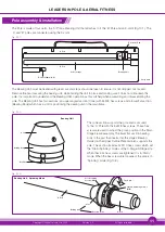
Upper Centre Plate
Slide the nose of the floor
plate under the upper
centre plate
Floor Plate
Locating Pins
Spring Catch
Locating Hole
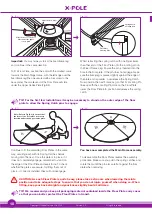
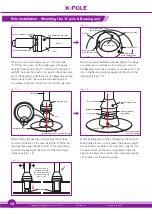
Important:
You must always start at the fixed frame leg
and continue in the same direction.
To fit a Floor Plate, position the end with the smallest curve
towards the Main Stage Frame, with the left edge over the
fixed frame leg (the one secured with a hex screw to the
base plate). The smaller end of the Floor Plate will slide
under the Upper Centre Plate (Fig.9.3).
Whilst retracting the spring catch with one finger lower
the other end of the Floor Plate onto the locating pin on
the Fixed Frame Leg. Ensure the pin is inserted into the
hole in the floor plate. If the pin does not engage, make
sure the frame leg is pressed tightly against the edge of
the plate and is parallel - now release the Spring Catch.
Now position the next Frame Leg so that its Locating Pin
lines up with the Locating Pin Hole on the Floor Plate,
lower the Floor Plate into position and release the spring
catch.
Fig. (9.3)
Fig. (9.4)
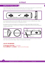
TIP: For the first few installations it may be necessary to stand on the outer edge of the floor
plate to allow the Spring Catch pins to engage.
Continue to fit the remaining Floor Plates in the same
way, securing each with its Spring Catches before
moving onto the next. Once the plate is in place, if it
does not completely engage, remember to stand on
the edge of the Floor Plate and exert force. To check
whether the plates are secure, try lifting them out of
place – if correctly installed, they will not disengage.
You have now completed the Main Frame assembly.
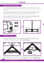
To disassemble the Floor Plates reverse the assembly
procedure. Make sure you pull in the spring catches and
rotate them until the pin arms are flat against the floor
plate when removing.
Fig. (9.5)
Fig. (9.6)
CAUTION: As each Floor Plate is quite heavy, please take extra care when lowering them into
position and take adequate steps to ensure that you do not injure yourself when doing so. When
fitting, keep your back straight and your knees slightly bent at all times.
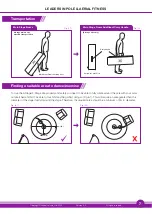
TIP: We recommend you keep all packaging material contained inside the Floor Plate carry cases
so that you can better protect the Floor Plates in transit.
Note: Refer to Fig (9.3) to ensure that
the front of the floor plate is securely
inserted under the upper centre plate.