


12
®
LEADERS IN POLE & AERIAL FITNESS
Copyright© Vertical Leisure Ltd. 2020 Version 3.0
All rights reserved.
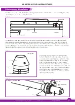
'A' Pole
Bearing Retaining Screw (M10) Domed
Protruding Screw
Slot
Bearing Unit
Static & Spinning Screw (M10)
Pole Retaining Screw (M8)
Cone
'A' Pole
Bearing Retaining Recess
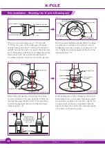
Pole installation - Mounting the 'A' pole & Bearing unit
Locating Screw
X
Top Plate
Bearing Carrier Ring
Bearing Retaining Screw
(M10) Domed
Bearing Retaining
Screw (M10) Domed
Bearing Retaining
Screw (M10) Domed
Static/Spin Hole
Fig. (11.1)
Fig. (11.2)
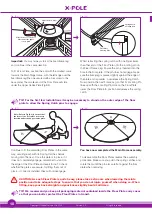
When you open your stage pole set – the pole tube
('A' POLE), that goes into the stage base, will already
have the 'bearing unit' (Fig.11.1) attached to the pole. It
will NOT be locked in position. An elastic rubber band will
be on the bearing to hold this in place. Please remove the
elastic rubber band, this will allow the bearing unit to
move freely. Take care it does not drop off the pole tube.
Next, look inside the Bearing Carrier Ring on the stage
top plate and you will see a pin sticking out. Look at
the Bearing unit on the pole and you will see a slot. The
pin on the Bearing carrier engages into the slot on the
bearing unit (Fig.11.2)
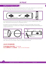
Pole Retaining Screw
(M8)
Bearing Body
Static & Spinning
Screw (M10)
Pole Holder unit
Bearing Retaining
Screw (M10) Domed
Locating Slot
Locating Screw
Fig. (11.3)
Fig. (11.4)
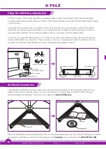
Whilst holding the bearing unit, take care that it does
not slide off the end of the pole, insert the 'A' POLE into
the stage base ensuring the bottom of the pole is firmly
seated in the bearing at the bottom of the main stage
frame base (Fig 11.5).
Whilst inserting the 'A' Pole and Bearing Unit into the
Main Stage Frame, you must keep the pole as upright
and vertical as possible so that it locates correctly into
the lower bearing in the main stage frame. Slide the
bearing unit down the pole into the carrier ensuring the
slot locates over the locating screw.
When the pole is
engaged correctly,
the pole will not have
as much movement
side to side.
Fig. (11.5)
Bearing