


Inspection and maintenance
61
Greenstar 2000 – 6 721 820 552 (2021/02)
9.6
Flue gas analysis
NOTICE
Combustion testing
▶ Combustion testing must be carried out by a competent person.
Testing must not be attempted unless the person carrying out the
combustion check is equipped with a calibrated flue gas analyser
conforming to BS 7967 and is competent in its use.
Flue gas analysis
▶ Ensure that the gas inlet pressure has been checked and is
satisfactory.
▶ Refit the test point plugs after the test has been completed.
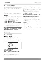
▶ Set the appliance to maximum and minimum output in chimney
sweep mode (
6.5 "Chimney sweep mode") for the flue gas
analysis checks.
▶ Check that the readings conform to those given in the following
tables. In addition to CO and CO/CO
2
ratio checks also check the
maximum and minimum CO
2
percentage reading.
Appliance combustion contents settings
Table 33 CO
2
settings
Table 34 CO
2
settings
If the CO
2
is out of tolerance then please check:
▶ The gas inlet pressure.
▶ The gas rate.
▶ The fan test pressure.
▶ The flue and air intake, plus any possible blockages in the condensate
disposal.
▶ The condition of burner.
▶ For leaks or obstructions in the exhaust paths.
▶ That the injector is clean.
After all checks have been completed and the CO
2
is still out of tolerance
then contact Worcester, Bosch Group helpline 0330 123 3366 before
making any adjustment to the gas valve.
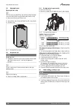
9.7
Checking the flue integrity
NOTICE
▶ Check flue joints are secure, the terminal and the terminal guard, if
fitted are clear and undamaged.
▶ Combustion testing must be carried out to BS 7967 by a competent
person. Testing must not be attempted unless the person carrying
out the combustion check is equipped with a calibrated Combustion
Analyser conforming to BS EN 50379 and is competent in its use.
Flue gas analysis
▶ Ensure that the gas inlet pressure has been checked and is
satisfactory.
▶ Refit the test point plugs after the test has been completed.
▶ Refer to chapter 6.10 "Checking flue integrity" and check that the
readings conform to those given, confirming flue system and
combustion circuit are ok.
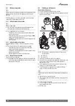
9.8
Cleaning the siphon and heat exchanger
WARNING
Gaskets and seals - gas related components
▶ Burner/electrode assembly gasket must be replaced if disturbed.
▶ Other gaskets/seals must be checked and replaced where necessary.
▶ Do not attempt the cleaning procedure unless new gaskets and seals
are available.
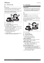
9.8.1
Cleaning the heat exchanger
There is an optional tool available to assist in cleaning the heat
exchanger, part number 7 733 600 091.
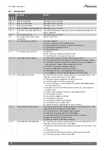
Checking the electrodes and cleaning the heat exchanger
CAUTION
Risk of burns due to hot surfaces!
Individual components of the appliance can become very hot even after
being shut down for a long time.
▶ Allow the appliance to cool down before carrying out any work.
▶ If necessary, wear protective gloves.
WARNING
Material damage due to hot flue gas! - Gaskets and seals - gas related
components
Hot flue gas can leak through defective gaskets, damage the appliance
and endanger safe operation.
▶ Burner/electrode assembly gasket must be replaced if disturbed.
▶ Other gaskets/seals must be checked and replaced where necessary.
▶ Do not attempt the cleaning procedure unless new gaskets and seals
are available.
▶ Ensure that the gaskets are positioned correctly.
CO
2
Reading
CO Reading
Natural Gas - Maximum rated Output
1)
1) Should be measured 10 minutes after firing the appliance
Between 9.0 and 10.8%
<250ppm
Natural Gas - Minimum rated Output
A minimum of 0.6 lower than the maximum reading
taken but above 8.2%
<250ppm
CO
2
Reading
CO Reading
LPG - Maximum rated Output
1)
1) Should be measured 10 minutes after firing the appliance
Between 10.6 and 11.0%
<250ppm
LPG - Minimum rated Output
A minimum of 0.3 lower than the maximum reading
taken but above 10.2%
<250ppm


