


Installation
Greenstar 2000 – 6 721 820 552 (2021/02)
36
5.1
Position the appliance
WARNING
▶
Ensure the mains gas supply is isolated before starting any work
and follow all relevant safety precautions.
Appliance positioning
▶ Ensure the appliance is mounted onto a flat, fixed rigid surface
capable of supporting the appliance weight.
▶ Ensure all aspects of the installation are considered when positioning
the appliance, flue run and discharge, condensate disposal, PRV
discharge etc.
WARNING
Damage to property!
Damage caused by drilling into pipes, electrical cables, damp proof
course or other hazards.
▶ Before drilling ensure that there are no obstructions or other hazards.
NOTICE
Damage to appliance!
Residue, metal shavings, and contaminants in the system pipe work can
damage the appliance.
▶ Flush the system pipe work thoroughly to remove all residue.
▶ Follow the instructions with respect to cleaning primary systems.
Running pipes to the appliance.
• The area around a rear flue outlet must be avoided.
5.1.1
Mounting bracket fixing
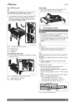
Wall mounting template
▶ The wall mounting template has been sized to allow for the minimum
clearances around the appliance, (
section 4.3.3 "Appliance
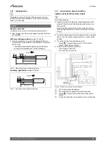
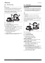
Fig. 41 Wall mounting template
1
Side exit flue example
2
Rear exit flue example
3
Wall mounting template
4
Primary fixing points
D
125mm
The appliance wall mounting template shows the relative positions of the
flue and the top fixings of the wall mounting bracket.
▶ Fix the wall mounting template [3] to the wall in the desired position.
▶ Drill the holes [4] through the template for the primary fixing points
as indicated on the template.
– Additional fixing points for the appliance will be indicated on the
wall mounting template.
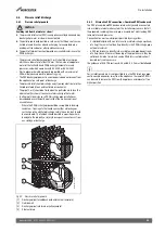
Flue outlet position.
The appliance wall mounting template has the flue centre lines for the
following flue systems:
• 60/100mm
• 80/125mm
Flue turret adaptor
▶ The flue turret adaptor has an in-built 3° angle giving the flue
assembly the rise from the appliance to ensure the condensate flows
back to the appliance.
Rear flue outlet [2].
▶ Mark centre line of flue to be used; the external diameter of the hole
can also be marked if required.
▶ If extensions are to be added then the complete flue must rise at an
angle of 3° from the appliance.
0010029478-001
2
3
4
1


