


Installation
39
Greenstar 2000 – 6 721 820 552 (2021/02)
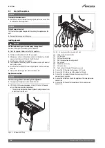
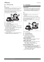
Connect PRV discharge pipe
It is recommended to fit the PRV pipework after isolation valves are
fitted; to provide more tool access for compression fittings.
▶ It is recommended to use the push-fit connector [2] supplied. This
provides easy installation, guards against potential harmful heat
transfer if soldering and allows the boiler to be removed from the
wall, if needed, with PRV pipework in place.
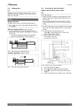
Fig. 45 Connecting to the PRV tail connection
[1]
PRV tail connection
[2]
Push-fit connector
[3]
PRV pipework
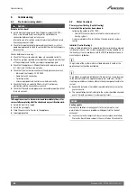
Connect condensate discharge pipe
▶ Connect the condensate discharge pipe to the appliance condensate
hose outlet connection.
Fig. 46 Connecting to the condensate outlet connection
[1]
Condensate hose outlet connection
[2]
Condensate discharge pipe
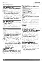
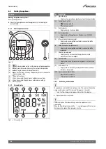
Filling the siphon
▶ Pour 200 to 250 millilitres of clean water through the inner flue
opening to fill the siphon before running the appliance.
Fig. 47 Filling the siphon
5.4
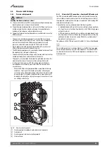
Flue turret/adaptor installation
NOTICE
Flue installation
▶ Refer to the Flue Kit Installation instructions provided with your flue
kit to correctly install the flue with this appliance.
▶ Do not exceed the maximum straight length for a horizontal or vertical
flue or a 60mm plume management system (if used) as stated in the
relevant Installation and Maintenance Instructions manual or
addendum.
Telescopic flue
▶ Cutting the flue to an exact measurement is not required as the
telescopic flue terminal can allow for some adjustment.
Apply silicone lubricant to sealing surfaces, to ease assembly of flue
components.
Refer to the manual supplied with the flue kit for complete installation
instructions.
▶ For plume management effective lengths and the effective flue
lengths,
chapter 4.4.
Additional notes and reminders:
• Ensure that all cut lengths are square and free from burrs.
• Ensure that the flue and seals are not damaged.
• The flue is sealed when assembled correctly, the components are
pushed fully home and secured.
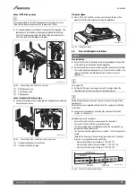
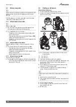
• The flue rises from the appliance at an angle of 3° or 52mm per metre
length.
• Support the flue at each flue extension joint and at each change of
direction, use suitable brackets and fittings:
– Flue bracket 100mm part number: 7 716 191 177.
– Flue brackets 100mm x 6 part number: 7 716 191 178.
– Flue bracket 125mm part number: 7 716 191 179.
Fig. 48 Slope for condensate disposal
0010033723-001
1
2
2
3
0010033725-001
1
2
0010033003-001
2
104mm
52mm
2,000mm
1,000mm
0010013472-001


