Manual 04121
ProAct I/II
Woodward
29
Control Outputs
Actuator Control
The actuator is connected to terminals 1 (+) and 2 (-). The polarity of this
connection must be correct if the actuator is to respond in the desired rotational
direction. The actuator cannot be reversed by changing the polarity because of
the factory-installed return spring. Use 4 mm² (12 AWG) wire to the actuator. The
total length of the pairs of wires between the actuator and the control and
between the battery and the control should not exceed 23 m (75 ft).
Speed Switches
Terminals 3, 4, and 5 provide the outputs from speed switches A, B, and C.
These outputs close a circuit to the power supply (+). The speed switches are
rated to 500 mA. The output will operate a signal lamp directly, or may be
connected to an intermediate relay to conduct heavier switch operations. The
switch is a low side switch which connects the device attached to the switch to
ground. The total length of the wire between the speed switches and the signal
lamp or relay should not exceed 8 m (26 ft).
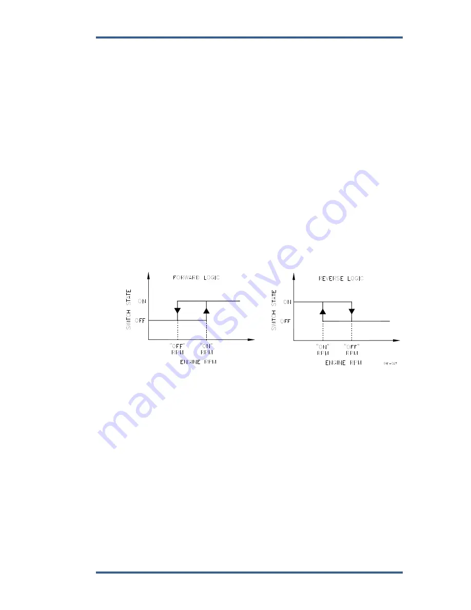
The switches are configured in Menu 3 and operate as shown in Figure 3-7.
Figure 3-7. Speed Switch Operation
Fault Lamp
Terminal 6 provides the output for the fault lamp indicator. This output closes a
circuit to the power supply (+) and is rated for 500 mA to indicate a fault. The
output will operate a signal lamp directly, or may be connected to an intermediate
relay to conduct heavier switch operations. The faults indicated are actuator
position feedback out of range (0.5 Vdc < Vposition < 4.5Vdc), actuator driver
circuit open, or actuator overcurrent. The total length of the wire between the
speed switches and the signal lamp or relay should not exceed 8 m (26 ft).
Actuator Position Feedback
Shielded wire must be connected to the Actuator Position Feedback terminals 7,
8, and 9. The shield must be continuous and grounded at the control end only to
prevent interference with the position feedback signal.
Summary of Contents for ProAct I
Page 10: ...ProAct I II Manual 04121 8 Woodward Figure 1 3 Example of ProAct II Actuator...
Page 11: ...Manual 04121 ProAct I II Woodward 9 Figure 1 4 Outline Drawing of ProAct I or II Actuator...
Page 12: ...ProAct I II Manual 04121 10 Woodward Figure 1 5 ProAct Wiring Diagram...
Page 13: ...Manual 04121 ProAct I II Woodward 11 Figure 1 6 Outline Drawing of ProAct Control Box...
Page 39: ...Manual 04121 ProAct I II Woodward 37 Figure 4 2 Typical Transient Response Curves...


