background image

TD_PCM1x_Packages_Function/Operation_08.04_GB 29 


NOTE 

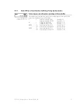
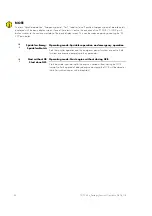
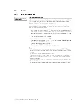
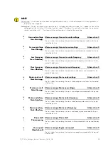
Discrete input – If a discrete input has been configured as alarm input, this will be displayed with its configured text in 

the display when triggered. 

Analog input – The text, assigned in the respective mask, is displayed as alarm message. An "!" appears in front of the 

configured text (for limit value 1 "Warning" and limit value 2 "Shutdown"). In case of a wire break, the measuring 
value is overwritten with "- -". An alarm with the set alarm class is issued at the same time. 


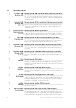
GB 

Gen.undervoltage 

Gen.-Unterspg. 

Alarm message: Generator undervoltage 

Alarm class: 3

The limit values for monitoring the generator undervoltage are under-run for the pe-
riod of delay time. 


GB 

Gen.overvoltage 

Gen.-Überspg. 

Alarm message: Generator overvoltage 

Alarm class: 3

The limit values for monitoring the generator overvoltage are exceeded for the pe-
riod of delay time. 


GB 

Low frequency 

Gen.-Unterfreq. 

Alarm message: Generator underfrequency  

Alarm class: 3

The limit values for monitoring the generator underfrequency are under-run for the 
period of delay time. 


GB 

Over frequency 

Gen.-Überfreq. 

Alarm message: Generator overfrequency 

Alarm class: 3

The limit values for monitoring the generator overfrequency are exceeded for the 
period of delay time. 


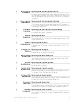
GB 

Mains-undervolt. 

Netz-Unterspg. 

Alarm message: Mains undervoltage  

Alarm class: 0

The limit values for monitoring the mains undervoltage are under-run for the period 
of delay time. 


GB 

Mains-overvolt. 

Netz-Überspg. 

Alarm message: Mains overvoltage 

Alarm class: 0

The limit values for monitoring the mains overvoltage are exceeded for the period 
of delay time. 


GB 

Mains-underfreq. 

Netz-Unterfreq. 

Alarm message: Mains underfrequency  

Alarm class: 0

The limit values for monitoring the mains underfrequency are under-run for the pe-
riod of delay time. 


GB 

Mains-overfreq. 

Netz-Überfreq. 

Alarm message: Mains overfrequency  

Alarm class: 0

The limit values for monitoring the mains overfrequency are exceeded for the pe-
riod of delay time. 


GB 

Phase shift 

Phasensprung 

Alarm message: Phase shift  

Alarm class: 0

The limit values for monitoring the phase shift are exceeded for the period of delay 
time. 


GB 

Over speed 

Überdrehzahl 

Alarm message: Engine overspeed  

Alarm class: 3

The limit values for monitoring the engine overspeed are exceeded for the period 
of delay time. 


Summary of Contents for PCM1x

Page 1: ...PCM1x Packages Pxx Genset Control Function Operation Softwareversion 4 3 ...

Page 2: ... 2 5 LC Display 15 3 Display 16 3 1 Measuring Values 16 3 1 1 First Display Line 16 3 1 2 Direction Of Power 17 3 1 3 Second Display Line 18 3 2 Service Display 20 3 2 1 Service Display On Synchronous Generators 20 3 2 2 Service Display On Asynchronous Generators 20 3 2 3 Status Of Power Circuit Breakers And Relays During Synchronization 21 3 3 Operating Conditions 22 3 4 Counter 25 3 4 1 Reset Ma...

Page 3: ... M 6 Figure 3 1 Direction of power 17 Tables Table 1 1 Manual Overview 5 Table 2 1 Function external operation mode selection 14 Table 4 1 Alarms Short acknowledgement 27 Table 4 2 Alarms Long acknowledgement Table for warning alarms 27 Table 4 3 Alarms Long acknowledgement Table for alarms causing a shutdown 27 Table 4 4 Alarms Text messages 28 ...

Page 4: ...e system Electronic controls contain static sensitive parts Observe the following precautions to prevent damage to these parts Discharge body static before handling the control with power to the control turned off contact a grounded surface and maintain contact while handling the control Avoid all plastic vinyl and Styrofoam except antistatic versions around printed circuit boards Do not touch the...

Page 5: ... reactive power load sharing including load management with automatic start stop of others and re dundant gensets Synchronization of one or two power circuit breakers CAN bus communications to engine controllers and plant management systems Intended Use The unit must only be operated according to the guidelines described in this manual The pre requisite for a proper and safe operation of the produ...

Page 6: ...infinitely adjusted via a rotary poten tiometer positioned on the left The configuration bushing is located on the left side of the item Please connect the direct configuration cable there FL CABLE RS232 U L1 L2 L3 10 10 STATUS ALARM PARAMETER V kV AL1 AL2 AL3 U fN PCM1 G Parallel 14 16 5 12 27 13 9 3 2 1 28 29 30 15 25 22 21 26 23 24 4 8 10 17 18 11 6 7 Figure 2 1 Front panel PCM1 G U L1 L2 L3 10...

Page 7: ...ute message 12 STATUS ALARM Confirm selection 13 U SELECT Switch display 13 U SELECT Increase digit 14 PARAMETER Activate setpoint value 14 PARAMETER Move one position to the right 15 Increase setpoint value 16 Reduce setpoint value 17 I GCB ON Close GCB manually 18 O GCB OFF Open GCB manually 19 I MCB ON PCM1 M Close MCB manually 20 O MCB OFF PCM1 M Open MCB manually 21 AUTOMATIC Activate AUTOMAT...

Page 8: ...and DI or operating mode stop engine and DI or operating mode yes close GCB and DI or operating mode open GCB and DI or operating mode PCM1 M close MCB and DI or operating mode PCM1 M open MCB and DI or operating mode raise setpoint value lower setpoint value Mode TEST start engine start load test end load test PCM1 M end load test raise setpoint value lower setpoint value Mode STOP LED test Confi...

Page 9: ...he corresponding outer LED flashes LED Configuration If in configuration mode the service display is ON and the dou ble voltage double frequency display is active the LEDs show the current phase angle between the two displayed voltages The green LED in the center of the 15 LEDs indicates that the measured phase angle between the voltage systems displayed is less than 12 electrical The phase angle ...

Page 10: ...e item this is processed ac cording to its alarm class The message and the type of alarm are shown on the LC display If this LED flashes a new alarm has occurred within the last two min utes Via brief acknowledgment this switches to continuous illumination and the centralized alarm horn is ceased A list of all alarms you find in the annex of this manual 10 GCB on Color green Reply GCB is closed Th...

Page 11: ...d for at least 5 seconds the counter that can currently be seen in the display is re set Configuration U SELECT With this push button the number at which the cursor is currently located is increased by one U SELECT The increase is re stricted by the admissible limits see list of parameters included in the appendix In case the maximum number is reached which can be set the number automatically retu...

Page 12: ...wer circuit breaker can depending on the power circuit breaker logic be opened or synchronization of the GCB can be aborted if started 19 20 PCM1 M MCB ON MCB OFF Color green red Close MCB open MCB only available in PCM1 M Note Only enabled if operating mode MANUAL or TEST has been selected MCB ON Depending on which power circuit breaker logic has been set the MCB can be closed by pressing the MCB...

Page 13: ... can be blocked via the discrete input D02 terminal 63 22 MANUAL Color gray Operating mode MANUAL Using MANUAL operating mode the push buttons can be activated to control the equipment manually The automatic control of the power circuit breakers and the genset are blocked Important automatic processes continue to remain in operation e g engine monitoring and the mains watchdog function for operati...

Page 14: ... input at terminal 64 is configured as control input using the parameter Op mode blocked by Ter 63 and energized it is possible for units with Package P01 from version 4 3010 to select the operation mode externally using the control inputs at terminals 127 and 128 The functionality is described in the follow ing table Operation mode blocked terminal 63 Input STOP terminal 127 Input AUTOMATIC termi...

Page 15: ...owledge push button The destruction of the engine cannot otherwise be ruled out 27 RESET Color blue Acknowledgement With this button the alarm messages are acknowledged i e the alarm indica tions on the LC display disappear and the Alarm LED goes out The operating variable display is set on the basic screen Alarm class F2 and F3 alarms can only be acknowledged in the STOP and MANUAL operating mode...

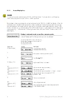
Page 16: ...he following measuring values are displayed depending on the LEDs UL1 UL2 UL3 xxxx generator voltage depending of the LEDs UL1 UL2 UL3 UL1 illuminates line to neutral voltage UL1 N UL2 illuminates line to neutral voltage UL2 N UL3 illuminates line to neutral voltage UL3 N UL1 UL2 illum line to line voltage UL1 L2 UL2 UL3 illum line to line voltage UL2 L3 UL3 UL1 illum line to line voltage UL3 L1 y...

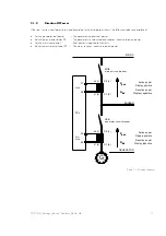
Page 17: ...es inductive re active power Positive mains real power Real power is supplied to the mains Inductive mains power factor ϕ The mains receives inductive re active power S1 K S2 L S2 L S1 K Active power Dispaly positive Reactive power Display inductive Active power Display positive Reactive power Display capazitive GCB generator circuit breaker MCB mains circuit breaker PCx 26 25 s1 k G s2 l 28 27 s1...

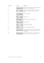
Page 18: ... Display in automatic mode second line measuring value Instead of xxxxxxxxxx the following measuring values are displayed the maximum generator current slave pointer the four alarm messages which occurred first the time the date P01 the energy counter kWh Succession Display Description 0 Basic display Gen 0 00 0000kW Generator power factor ϕ Generator actual real power 1 max Gen strom Slave pointe...

Page 19: ...Generator active energy 10 Betrieb 000000h Operating hours 11 Wartung in 0000h Time remaining until the next maintenance call 12 Startzahl 00000 Engine start counter 13 Batterie 00 0 V Battery voltage supply voltage 14 Teilnehmer 00 CAN bus participants on the load share 15 xxxxxxxxxxxxxxxx Alarm messages maximum of 4 further alarm messages are displayed first after one or more of the first four h...

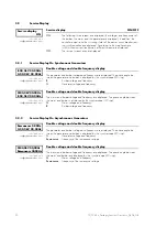
Page 20: ...enerator voltage and frequency M 00 0kV 00 00Hz B 00 0kV 00 00Hz only visible while configuration mode is active Double voltage and double frequency display The mains and busbar voltage and frequency are displayed The phase angle between the mains and busbar is displayed by the synchroscope LED strip M Mains voltage and frequency B Busbar voltage and frequency 3 2 2 Service Display On Asynchronous...

Page 21: ...he actual relay states of the controller outputs and the signals to the power circuit breakers during synchronization f Frequency controller RAISE Terminal 8 9 Frequency controller LOWER Terminal 8 10 U Voltage controller RAISE Terminal 11 12 Voltage controller LOWER Terminal 11 13 MCB On Connect pulse of the MCB Terminal 16 17 Off Disconnect pulse of the MCB Terminal 39 40 GCB On Connect pulse of...

Page 22: ...s generators The GCB is closed black if generator voltage is present and busbar voltage is not present GB Dead bus st MCB D Schwarzst NLS PCM1 M Operating mode Close MCB black Synchronous generators The MCB is closed black if mains voltage is present and busbar voltage is not present GB Start D Anlassen Operating mode Start engine The engine is started by reason of an automatically e g mains failu...

Page 23: ...st is carried out after the button GCB ON was operated GB Emergency run D Notstrom Operating mode Emergency Emergency power was identified and carried out GB Mains settl 000s D Netzber 000s Operating mode Mains settling time The displayed message shows the mains settling time following a mains failure There is shown the remaining mains setting time GB Sprinkler D Sprinklerbetrieb Operating mode Sp...

Page 24: ...again by actuating the RE SET push button GB Sprinkler Emerg D Sprinkler Notstr Operating mode Sprinkler operation and emergency operation Both the sprinkler operation and the emergency power functions are active Both functions are executed according to their parameters GB Start without CB D Start ohne GLS Operating mode Start engine without closing GCB Via the discrete input terminal 6 the engine...

Page 25: ...ry out the maintenance of the installation 3 Acknowledge the maintenance call as follows Navigate by using the button STATUS ALARM up to display Wartung in 000h Press the button U SELECT for 10 seconds The new maintenance interval is indicated Press the button RESET with it the alarm message is reset Notes Notes Notes Notes Up to software version 3 4xxx acknowledgement occurs via button RESET Betw...

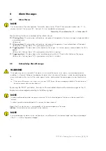
Page 26: ...D group alarm relay horn shutdown 4 2 Acknowledge Alarm Messages WARNING The engine may start unintentionally if an alarm which caused the engine to shut down is acknowledged and an enabling is still present Before acknowledging the alarm check the cause of the alarm in order to protect operating personnel located in the vicinity of the system against injuries and to protect the engine against uni...

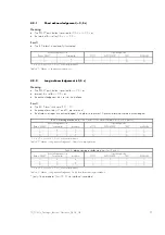
Page 27: ...up alarm relays F1 and F3 are reset and the display messages are acknowledged if no alarms are present A present alarm cannot be acknowledged Table for warning alarms alarm class 0 and 1 if no alarm of alarm class 2 or 3 is present Acknowledgement via Operating mode Button RESET Terminal 6 Interface STOP AUTOMATIC TEST MANUAL 1 x x 1 1 1 1 0 1 x 1 1 0 0 0 0 1 0 1 0 0 1 set 0 not set x 0 or 1 witho...

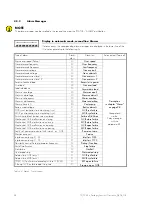
Page 28: ...ains phase shift F0 Vectorjump Battery undervoltage F1 Batt undervolt GCB synchronization time monitoring syn F1 GCB syn failure MCB synchronization time monitoring syn F1 MCB syn failure Switching to black busbar time monitoring F1 Failure df dVmax Mechanical GCB malfunction on closing F1 GCB close failure Mechanical MCB malfunction on closing F1 MCB close failure Mechanical GCB malfunction on op...

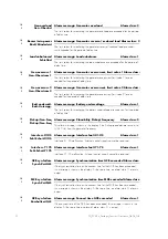
Page 29: ...od of delay time GB Over frequency D Gen Überfreq Alarm message Generator overfrequency Alarm class 3 The limit values for monitoring the generator overfrequency are exceeded for the period of delay time GB Mains undervolt D Netz Unterspg Alarm message Mains undervoltage Alarm class 0 The limit values for monitoring the mains undervoltage are under run for the period of delay time GB Mains overvol...

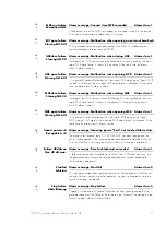
Page 30: ... battery undervoltage are under run for the period of delay time GB Pickup Gen Freq D Pickup Gen Freq Alarm message Plausibility Pickup Frequency Alarm class 3 This alarm message is shown in the display if the Pickup speed deviates excessive ly 10 Hz from the generator frequency GB Interf err X1X5 D Fehl Schnit X1X5 Alarm message Interface fault X1 X5 Alarm class 1 Interface X1 X5 malfunction Exte...

Page 31: ...t the same time an alarm class F1 alarm is output GB MCB open failure D Störung NLS AUF Alarm message Malfunction when opening MCB Alarm class 1 If it is present 2 seconds following the Command MCB open pulse Reply MCB is open is still present the message MCB open failure is displayed At the same time an alarm class F1 alarm is output GB Import power 0 D Bezugsleist 0 Alarm message Incoming power ...

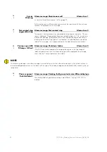
Page 32: ...is not reached no underfrequency can be de tected This message is not suppressed due to the delayed engine monitoring GB P ramp open GCB D P Rampe GLS auf Alarm message Shutdown failure Alarm class 3 If the GCB can not be opened after stopping the engine in the time range of add stop ramp max time this alarm message will be displayed this message shows that the P control potentially has a fault NO...

Page 33: ...TD_PCM1x_Packages_Function Operation_08 04_GB 33 ...

Page 34: ... Kempen Germany Phone 49 0 21 52 145 1 Internet Homepage http www woodward seg com Documentation http doc seg pp com Sales Phone 49 0 21 52 145 635 Telefax 49 0 21 52 145 354 e mail kemp electronics woodward com Service Phone 49 0 21 52 145 614 Telefax 49 0 21 52 145 455 e mail kemp pd woodward com ...

Reviews: