


8
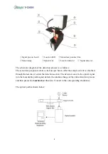
①
Signal process board
②
Location LED
③
Xenon lamp connect line
-
④
Xenon lamp
-
⑤
Optical lens
-
⑥
Location detector
⑦
Signal detector
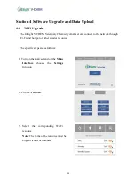
The schematic diagram of the detection process is as follows:
The xenon lamp exposure emits a stroboscopic beam. After the sample cuvette is absorbed
through the test disc, it enters the detection section. The detector converts the optical signal
into the measurable point signal, detects the solution change of the entire detection process
and then passes the
Lambert-beer
theorem. Convert to the corresponding absorbance.
The optical path is shown below:
Summary of Contents for InSight V-CHEM
Page 1: ...Veterinary Chemistry Analyser Service Manual...
Page 9: ...3 Back View Right View...
Page 42: ...36...


