background image

Maintenance and repair

INTORQ | BA 14.0197 | 04/2016

44

7.4

Spare-parts list

Only parts with item numbers are available.
-

The item numbers are only valid for the standard design.

Please include the following information with the order:
-

Order number of the brake

-

Position number of the spare part

Abb. 17

Spring-applied brake BFK464-

 S / S.1 / S.2

Item

Designation

Variant

1

Stator, complete

Voltage

3

Complete rotor
Rotor, complete noise-reduced

4

Hub

Bore diameter

6

Flange

10

Set of fastening screws
Cylinder head screw DIN912

for mounting to the motor
for flange with through hole

12

Complete manual release

13

Cover ring

18

Noise reducer

Summary of Contents for WSG-TB.3 series

Page 1: ...on 0 01 Page 1 Subject to changes without notice Subject to changes without notice EN Gearless Lift Machines WSG TB 3 WSG TB 5 Reprinting translation or reproduction in any form whether in part or in...

Page 2: ...s the right to correct or change the contents of this manual and these product details without prior notice We expressly reserve the right to make technical changes which improve the lift machines or...

Page 3: ...intervals 17 6 3 Regreasing the bearings 17 6 4 Emergency evacuation 18 6 5 Testing the brake system to EN 81 19 6 6 Replacing the measuring system 20 6 7 Trouble shooting 21 7 Type code 22 8 Technic...

Page 4: ...be operated under the conditions described in this manual and with due regard to their perfor mance limits 1 3 Scope of delivery The WSG TB lift machines are customised to meet individual requirement...

Page 5: ...nauthorised opening and tampering may result in injuries to persons and property The machines are not designed for direct connection to the three phase system but are to be operated via an electronic...

Page 6: ...he nameplate of the lift machine is on the motor frame 3 Product overview Type code of lift machine Rated voltage Rated speed Rated torque Serial no Rated frequency Weight Drive Code Item Part WSG TB...

Page 7: ...of exposure Avoid excessive storage periods recommendation max one year After prolonged storage 3 months rotate the motor in both directions at a low speed 20 min 1 to allow the grease to distribute...

Page 8: ...calculations to check the base frame or foundation loads before installing the lift machine Warning Cover the machine and especially the brakes when doing any machining or dust producing work in the s...

Page 9: ...their specific application and for the relevant voltages and currents sufficiently dimensioned connecting cables torsion strain and shear relief as well as anti kink protection are provided the protec...

Page 10: ...nverter with a switching frequency of 12 kHz The PTC resistor embedded in the winding must be evaluated in an appropriate manner in the control system or the frequency inverter to protect the motor fr...

Page 11: ...not exceed 2 5 V DC Cable cross section required The currents specified under the machine data refer to duty type S3 40 This must be taken into account when selecting the cable cross section required...

Page 12: ...plug Alternatively the machines can be equipped with ECN 413 or ERN 487 encoders from Heidenhain GmbH We can also provide other measuring systems on request Use a shielded cable to connect the Heiden...

Page 13: ...ero speed and the switching noise of the brake is negligible When braking in the event of a breakdown emergency stop or during an inspection drive the switching should be performed from the DC side si...

Page 14: ...ection As an option the electrical connection of the brake made by a 9 pole power connector mounted on the brake A type B ST A 908 FR11 85 001A 000 connector from intercontec can be used for example a...

Page 15: ...switching and separate control of the partial brakes K1 and K2 must swith simultaneously Brake connector 2 x Overexcitation rectifier Must be installed in the contol cabinet to the 2 nd partial brake...

Page 16: ...mperature monitoring devices e g by interrupting the temperature monitoring circuit Check the brake connection and the proper functioning of the brake monitoring switches Ensure that the brake operate...

Page 17: ...ntal loosening 6 2 Maintenance intervals Dimension Tightening torque Nm Strength class 8 8 10 9 12 9 M4 2 8 4 1 4 8 M5 5 5 8 1 9 5 M6 9 6 14 16 M8 23 34 40 M10 46 67 79 M12 79 115 135 M16 195 290 340...

Page 18: ...sen shown in the following pictures Danger All actions for evacuation in case of emergency have to be done by qualified service personnel Manual lifting rods machine room Brake manual release remotell...

Page 19: ...ld be tested with the car about halfway down the shaft If any motor short circuit connections have been made these should be deactivated so that the brake effect can be tested independently Warning Wh...

Page 20: ...05 2018 Statut 0 01 Page 20 Subject to changes without notice Subject to changes without notice EN 1 Remove the measurement system connector if used 2 Unscrew the clamping screw until the clamping be...

Page 21: ...ing voltage supply voltage Remove mechanical blocking Replace overexcitation rectifier Delay in braking system release Overexcitation rectifier defective Replace overexcitation rectifier Braking syste...

Page 22: ...1 with DT 100 mm v 0 63 m s suspension 2 1 38 382 min 1 with DT 100 mm v 1 0 m s suspension 2 1 X5 X6 X7 Traction sheave design Traction sheave diameter width groove design groove geometry X8 X9 Vari...

Page 23: ...Max altitude max 1 000 m derating required at higher altitudes Ambient temperature 5 C 40 C Max rel humidity 85 at 20 C no moisture condensation Dual circuit fail safe brake Motor type WSG TB 3 WSG T...

Page 24: ...5 D T 100 100 A 260 325 B 402 5 467 5 C 653 711 Z 100 100 Masse weight m G kg 111 123 Tr gheitsmoment inertia J G kgm 2 0 054 0 064 Achskraft bis zu shaft loads up to F S kN 24 Gearless Lift Machine W...

Page 25: ...CN 413 EnDat SSI 503 325 021 xx D Pack Arkel ADrive CT unidrive SP ECN 413 EnDat SSI 502 452 021 xx emotron Dietz DSV 5445 ECN 413 EnDat SSI 501 112 022 xx Fuji Frenic ECN 413 EnDat 502 679 022 xx KEB...

Page 26: ...1 4 V1 No 2 3 W1 No 3 PE gn ge gn ye C T1 No 5 BR1 BRK D T2 No 6 BR2 BRK 508 828 A21 xx A 1 1 5mm2 IS3 40 25A A 2 2 5mm2 IS3 40 35A Gearless Lift Machine WSG TB Operating Instructions Code GM 8 004610...

Page 27: ...Alternatively another simple version of the manual releasing device is available for lifts with a machine room The brake can be fitted with a manual brake releasing device on customer request The dev...

Page 28: ...cable for releasing can be delivered if required The standard length of the Bowden cable is 3 m Other lengths on request Installation Install the manual brake releasing device with the brake disconnec...

Page 29: ......

Page 30: ......

Page 31: ......

Page 32: ...TB Traction sheave shaft Annex calculation of the shaft L A L B 6218 2RS1 90 160 30 60 5 50kN 6218 2RS1 90 160 30 60 5 50kN q S q S q S q S q S F M m R m B M n M n M n M n M n M n M br M bi 51 5 37 3...

Page 33: ......

Page 34: ...pe s center to rope s center m 3 14 n Rotary speed rpm i Ratio of the car suspension Maximum tripping rotary speed of the traction sheave 700 rpm 1 2 Use as braking element part of the protection devi...

Page 35: ...ification drawing no 5019864 or 5019869 including stamp dated 2016 03 18 shall be in cluded to the EU type examination for the identification and information of the general construction and operation...

Page 36: ...f 2015 12 02 Page 1 of 1 Authorised Manufacturer of Serial Production Production Sites valid from 2016 03 18 Company INTORQ GmbH Co KG Address W lmser Weg 5 31855 Aerzen Germany Company INTORQ Shangha...

Page 37: ......

Page 38: ......

Page 39: ......

Page 40: ...ry speed as outlined above taking into account traction sheave diameter and car suspension v n i v Tripping rated speed m s DTS iameter of the traction sheave from rope s center to rope s center m 3 1...

Page 41: ...ue has to be secured against unauthorized adjustment e g sealing lacquer 2 5 The identification drawing no 5019881 or 5019894 or 5019902 or 5019904 or 5019936 or 5019937 including stamp dated 2016 03...

Page 42: ...f 2015 12 02 Page 1 of 1 Authorised Manufacturer of Serial Production Production Sites valid from 2016 03 18 Company INTORQ GmbH Co KG Address W lmser Weg 5 31855 Aerzen Germany Company INTORQ Shangha...

Page 43: ......

Page 44: ......

Page 45: ......

Page 46: ......

Page 47: ......

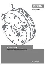
Page 48: ...www intorq com setting the standard www intorq com INTORQ BFK464 Electromagnetically Released Spring Applied Brake Translation of the Original Operating Instructions...

Page 49: ...ptions BFK464 17S BFK464 18S BFK464 18S 2 BFK464 19S BFK464 20S BFK464 20S 1 BFK464 22S BFK464 25S BFK464 25S 1 BFK464 28S INTORQ B FK A A B C D D E Legend for the product key INTORQ BFK464 Product gr...

Page 50: ...Rated holding power Hub diameter Packaging date Model identification CE mark Note Name plate Example Manufacturer CE mark Type see product key EC type examination identification Rated holding voltage...

Page 51: ...ter 33002149 3 0 08 2012 TD09 Supplement of the model identification number for the sizes 18S 19S and 28S Revision of the operating times Supplemented by versions 18S 2 and 25S 1 Change of the phone a...

Page 52: ...3 Rating design data 18 3 4 Switching energy operating frequency 19 3 5 Emissions 20 4 Mechanical installation 21 4 1 Important notes 21 4 2 Necessary tools 21 4 3 Assembly 22 4 4 Installation procedu...

Page 53: ...always be in a complete and readable condition 1 2 Terminology used 1 3 Conventions in use This document uses the following styles to distinguish between different types of information Term In the fol...

Page 54: ...n energy for one time switching thermal parameter of the brake QR J Braking energy friction energy QSmax J Max permissible friction energy for cyclic switching depending on the switch ing frequency Rm...

Page 55: ...rom the start of torque rise until reach ing the braking torque tue s Over excitation time U V Voltage UH V DC Holding voltage after voltage change over UL V DC Release voltage before voltage change o...

Page 56: ...completeness immediately to INTORQ GmbH Co KG 1 7 Disposal The spring applied brake consists of different types of material Recycle metals and plastics Ensure professional disposal of assembled circui...

Page 57: ...ally 1 9 Legal regulations Liability The information data and notes in these Operating Instructions met the state of the art at the time of printing Claims referring to drive systems which have alread...

Page 58: ...ied product characteristics Only qualified skilled personnel are permitted to work on and with INTORQ components According to IEC 60364 or CENELEC HD 384 qualified skilled personnel are persons who ar...

Page 59: ...beyond their corresponding power limits Any other use or excessive usage is considered improper Possible applications of the INTORQ spring applied brake Humidity no restrictions In the event of conden...

Page 60: ...ith two friction surfaces The braking torque is ap plied through two separate braking circuits both electrical and mechanical via several compression springs 1 2 in the form of generated friction The...

Page 61: ...e release When the brakes are applied an air gap sL is present between the stator 1 and the armature plate seg ment 1 To release the brake the coils 8 of the existing magnetic circuit are supplied wit...

Page 62: ...planning notes The brakes are dimensioned in such a way that the given rated torques are reached safely after a short run in process However as the organic friction linings used do not all have identi...

Page 63: ...late 6 Flange Type Air gap Perm wear Rotor thickness Stator weight complete sLN 0 05 mm sLmax mm mm min mm max mm m kg BFK464 17S 0 4 0 6 0 2 12 7 13 12 BFK464 18S 15 BFK464 18S 2 14 5 BFK464 19S 15 7...

Page 64: ...22S 250 6 x M10x1201 14 19 5 71 BFK464 25S 278 6 x M10x110 6 x M10x1301 18 22 5 BFK464 25S 1 BFK464 28S 314 M16 6 x M16x120 6 x M16x130 30 27 5 206 206 Tab 1 Dimensions of the BFK464 S S 1 S 2 Type Vo...

Page 65: ...ng torque at a constant speed of rotation U Voltage Type Rated torque1 Max perm switching energy Transitional switching frequency Operating times ms at sLN and 0 7 IN 2 Max speed4 MK QE Shue Engaging...

Page 66: ...before the motor is at standstill AC switching is also possible not applicable to emergency braking In this case the engagement times increase approximately by a factor of 5 for connection refer to 31...

Page 67: ...ge Heat Since the brake converts kinetic energy as well as mechanical and electrical energy into heat the surface temperature varies considerably depending on the operating conditions and possible hea...

Page 68: ...sert for hexagonal socket Allen screws Open jawed spanner Allen key for transport safety bolts Sleeve bolts Manual release nuts Measuring range Nm Width across flats mm Width across flats mm Width acr...

Page 69: ...pring applied brake 2 Check for completeness 3 Check the name plate data especially the rated voltage 4 3 3 Overview Brake size Minimum requirements Use as counter friction surface Material1 Evennes s...

Page 70: ...haft 3 Secure the hub against axial displacement for example by using a circlip 4 2 NOTICE The toothed hub and screws must not be lubricated with grease or oil NOTICE When you have ordered a version w...

Page 71: ...friction face Abb 5 Assembly without counter friction face Install the counter friction faces Abb 6 Assembly of the flange 1 Hold the flange 6 to the end shield 15 2 Align the through holes in the fl...

Page 72: ...by the manufacturer In the following sections only assembly for the versions with flange will be described Assembly of the complete stator Abb 8 Mounting the complete stator 1 Push the complete stator...

Page 73: ...10 using a feeler gauge and compare the values to the values for sLN in the table 16 If sL 16 is not within the tolerance readjust the air gap Air gap sL 1 1 Stator 6 Flange 10 Cylinder head bolt 2 Ar...

Page 74: ...7 4 Check the air gap sL near the bolts 10 with a feeler gauge sLN 16 5 Repeat the adjustment procedure if the deviation of sLN is too large WARNING Danger rotating parts Switch off the voltage The dr...

Page 75: ...g shield DANGER Brake may fail If the manual release is not adjusted correctly the brake may fail Possible consequences Severe injuries or material damage Protective measure Ensure that the dimension...

Page 76: ...wdriver 2 Put the lever 12 1 onto the brake 14 3 Place four cup springs 12 6 in alternate directions in each of the four sleeves 12 7 Finally insert the sleeves into the holes in the lever 12 1 NOTICE...

Page 77: ...if required The brake is not energised during adjustment 1 1 Stator complete 6 Flange 12 1 Lever 2 Armature plate Type sLN 0 05 mm s 0 1 mm BFK464 17S 0 4 5 3 BFK464 18S BFK464 18S 2 BFK464 19S BFK464...

Page 78: ...nds to the data on the name plate NOTICE If an emergency stop is carried out without the required suppressor circuit the control unit may be destroyed Observe the correct polarity of the suppressor ci...

Page 79: ...f wave rectifiers are used to supply electromagnetic DC spring applied brakes which are ap proved for the use with such rectifiers Other use is only permitted with the approval of INTORQ Once a set ov...

Page 80: ...8S BFK464 18S 2 BFK464 19S BFK464 20S BFK464 20S 1 BFK464 22S BFK464 25S BFK464 25S 1 BFK464 28S BEG 561 440 130 400 10 360 180 BFK464 17S BFK464 18S BFK464 18S 2 BFK464 19S BFK464 20S BFK464 20S 1 BF...

Page 81: ...bridge rectification 0 9 x U1 Output voltage for half wave rectification 0 45 x U1 Ambient temperature storage operation C 25 70 Type Input voltage U1 40 Hz 60 Hz Max current Imax Overexcitation time...

Page 82: ...mbly with metal surface good heat dissipation 2 For other assembly e g adhesive 5 3 Electrical connection DANGER There is a risk of injury by electrical shock The brake must only be electrically conne...

Page 83: ...d breakaway torque is common in particular after long downtimes in humid environments where temperatures vary Check the braking torque if the brake is inserted on the customer s friction surfaces If t...

Page 84: ...to the holding voltage see table 5 A deviation of 10 is permissible 7 Check the air gap sL It must be zero and the rotor must rotate freely 8 Check the switching status of the microswitch see table 6...

Page 85: ...ive must be able to be turned freely A low residual torque is permitted 15 Release the lever Torque must be available The preparations for commissioning are completed 6 3 Commissioning 1 Switch on dri...

Page 86: ...orque Measure the DC voltage at the brake The measured DC voltage after the over excitation time see bridge half wave rectifier 34 must correspond to the holding voltage see 33 A deviation of 10 is pe...

Page 87: ...E Braking torque reduction The air gap must not be re adjusted after it has been correctly adjusted during the initial installation of the brake on the motor This could result in a loss of braking tor...

Page 88: ...s and brake loads must be de fined for every application For the spring applied brakes the maintenance intervals and maintenance oper ations listed in the table below must be followed The maintenance...

Page 89: ...ly Refer to 43 for the description NOTICE Brakes with defective armature plates socket head cap screws springs or counter friction faces must always be replaced completely Generally observe the follow...

Page 90: ...7 Replace the hub if it is worn 8 Check the friction surface on the bearing shield In case of strong scoring at the flange replace the flange In case of strong scoring on the bearing shield rework th...

Page 91: ...with the order Order number of the brake Position number of the spare part Abb 17 Spring applied brake BFK464 S S 1 S 2 Item Designation Variant 1 Stator complete Voltage 3 Complete rotor Rotor comple...

Page 92: ...600 mm ________ mm from 100 1000 mm in 100 mm steps from 1000 2500 mm in 250 mm steps Manual release mounted Armature plate Standard Microswitch Monitoring the switching function Switching noises Damp...

Page 93: ...he values If resist ance is too low replace the complete stator Check the coil for short to ground using a multimeter If there is a short to ground replace the complete stator Check the brake voltage...

Page 94: ...cessary 27 Rotor thickness too small Rotor has not been replaced in time Replace the rotor 43 Voltage is not zero during the functional test 36 Microswitch incorrectly wired Check and correct the wiri...

Page 95: ...Notes INTORQ BA 14 0197 04 2016 48 Notes...

Page 96: ...Co Ltd No 600 Xin Yuan Nan Road Building No 6 Zone B Nicheng town Pudong 201306 Shanghai 86 21 20363 810 86 21 20363 805 info cn intorq com INTORQ US Inc USA 300 Lake Ridge Drive SE Smyrna GA 30082 US...

Page 97: ...www intorq com setting the standard www intorq com INTORQ BFK464 Translation of the Original Operating Instructions...

Page 98: ...bore hole options BFK464 17S BFK464 18S BFK464 19S BFK464 20S BFK464 20S 1 BFK464 22S BFK464 25S BFK464 25S 1 BFK464 28S INTORQ B FK A A B C D D E Legend for the product key INTORQ BFK464 Product gro...

Page 99: ...olding power Hub diameter Model identification CE mark Addition Nameplate Example Manufacturer CE mark Type see product key Model identification Rated holding voltage Rated holding power Hub diameter...

Page 100: ...ted data design data 17 3 4 Switching energy switching frequency 18 3 5 Emissions 19 4 Mechanical installation 20 4 1 Important notes 20 4 2 Necessary tools 20 4 3 Assembly 21 4 4 Installation procedu...

Page 101: ...e in a complete and perfectly readable condition 1 2 Terminology used 1 3 Conventions in use This document uses the following styles to distinguish between different types of information Term In the f...

Page 102: ...at energy QE J Max permissible friction energy for one time switching thermal parameter of the brake QR J Braking energy friction energy QSmax J Maximally permissible friction energy for cyclic switch...

Page 103: ...ms Rise time of the braking torque time from the start of torque rise until reach ing the braking torque tue s Overexcitation time U V Voltage UH V DC Holding voltage after voltage change over UL V D...

Page 104: ...ncies incompleteness immediately to INTORQ GmbH Co KG 1 7 Disposal The spring applied brake consists of different types of material Recycle metals and plastics Ensure professional disposal of assemble...

Page 105: ...lly 1 9 Legal regulations Liability The information data and notes in these Operating Instructions met the state of the art at the time of printing Claims referring to drive systems which have already...

Page 106: ...haracteristics Only qualified skilled personnel are permitted to work on and with INTORQ components According to IEC 60364 or CENELEC HD 384 qualified skilled personnel are persons who are familiar wi...

Page 107: ...yond their corresponding power limits Any other use or excessive usage shall be deemed improper Possible applications of the INTORQ spring applied brake Humidity no restrictions In the event of conden...

Page 108: ...brake with two friction surfaces The braking torque is ap plied through two separate braking circuits both electrical and mechanical via several compression springs 1 2 in the form of generated fricti...

Page 109: ...braking torque and low wear The braking torque is transmitted between the hub 4 and the rotor 3 via gear teeth 3 1 3 Brake release When the brakes are applied an air gap sL is present between the sta...

Page 110: ...lanning notes The brakes are dimensioned in such a way that the specified rated torques are reached safely after a short run in process However as the organic friction linings used do not all have ide...

Page 111: ...rmature plate 6 Flange Type Air gap Perm wear Rotor thickness Stator weight complete sLN 0 05 mm sLmax mm mm min mm max mm m kg BFK464 17S 0 4 0 6 0 2 12 7 13 12 BFK464 18S 15 BFK464 19S 15 7 16 18 8...

Page 112: ...0S 1 BFK464 22S 250 6 x M10x1201 14 19 5 71 BFK464 25S 278 6 x M10x110 6 x M10x1301 18 22 5 BFK464 25S 1 BFK464 28S 314 M16 6 x M16x120 6 x M16x130 30 27 5 206 206 Tab 1 Dimensions of the BFK464 S S 1...

Page 113: ...braking torque Mdyn Braking torque at a constant speed of rotation U Voltage Type Rated torque1 Max perm switching energy Transitional switching frequency Switching times ms at sLN and 0 7 IN 2 Max sp...

Page 114: ...dstill AC switching is also possible not applicable to emergency braking In this case the engagement times increase approximately by a factor of 5 refer to 31 for connection 3 4 Switching energy switc...

Page 115: ...Heat Since the brake converts kinetic energy as well as mechanical and electrical energy into heat the surface temperature varies considerably depending on the operating conditions and possible heat d...

Page 116: ...rench Insert for hexagonal socket Allen screws Open jawed spanner Allen key for transport safety bolts Sleeve bolts Manual release nuts Measuringrange Nm Width across flats mm Width across flats mm Wi...

Page 117: ...spring applied brake 2 Check for completeness 3 Verify the nameplate data especially the rated voltage 4 3 3 Overview Brake size Minimum requirements Use as counter friction surface Material1 Evenness...

Page 118: ...haft 3 Secure the hub against axial displacement for example by using a circlip 4 2 NOTICE The toothed hub and screws must not be lubricated with grease or oil NOTICE When you have ordered a version w...

Page 119: ...friction face Fig 5 Assembly without counter friction face Install the counter friction faces Fig 6 Assembly of the flange 1 Hold the flange 6 to the end shield 15 2 Align the through holes in the fl...

Page 120: ...facturer In the following sections only assembly for the versions with flange will be described Assembly of the complete stator Fig 8 Mounting the complete stator 1 Push the complete stator 1 onto the...

Page 121: ...bolts 10 using a feeler gauge and compare the values to the values for sLN in the table 15 If sL 15 is not within the tolerance readjust the air gap 1 1 Stator 6 Flange 10 Cylinder head bolt 2 Armatu...

Page 122: ...es refer to table 16 4 Check the air gap sL near the bolts 10 with a feeler gauge sLN 15 5 Repeat the adjustment procedure if the deviation of sLN is too large WARNING Danger rotating parts Switch off...

Page 123: ...ield DANGER The brake may fail If the manual release is not adjusted correctly the brake may fail Possible consequences Severe injuries or material damage Protective measure Ensure that the dimension...

Page 124: ...dy been removed Use a suitable tool to screw them in with a tightening torque of 10 Nm for sizes 17S 19S 20 Nm for sizes 20S 25S or 40 Nm for size 28S NOTICE The assembly of the manual release is carr...

Page 125: ...ntil they are flush against the sleeves 12 7 9 Connect the brake to a suitable power supply and switch on the voltage electrical release 10 Tighten the nuts 12 8 using a tightening torque of 4 Nm for...

Page 126: ...S BFK464 19S BFK464 20S 360 1 turn BFK464 20S 1 BFK464 22S BFK464 25S BFK464 25S 1 BFK464 28S 0 5 300 5 6 of a turn DANGER The brake may fail If the manual release is not adjusted correctly the brake...

Page 127: ...orresponds to the nameplate data NOTICE If an emergency stop is carried out without the required suppressor circuit the control unit may be destroyed Observe the correct polarity of the suppressor cir...

Page 128: ...are used to supply electromagnetic DC spring applied brakes which are ap proved for the use with such rectifiers Other use is only permitted with the approval of INTORQ Once a set over excitation time...

Page 129: ...17S BFK464 18S BFK464 19S BFK464 20S BFK464 20S 1 BFK464 22S BFK464 25S BFK464 25S 1 BFK464 28S BEG 561 440 130 400 10 360 180 BFK464 17S BFK464 18S BFK464 19S BFK464 20S BFK464 20S 1 BFK464 22S BFK46...

Page 130: ...bridge rectification 0 9 x U1 Output voltage for half wave rectification 0 45 x U1 Ambient temperature storage operation C 25 70 Type Input voltage U1 40 Hz 60 Hz Max current Imax Over excitation tim...

Page 131: ...mbly with metal surface good heat dissipation 2 For other assembly e g adhesive 5 3 Electrical connection DANGER There is a risk of injury by electrical shock The brake must only be electrically conne...

Page 132: ...breakaway torque is common in particular after long downtimes in humid environments where temperatures vary Check the braking torque when the brake is being used on the customer s friction surfaces If...

Page 133: ...to the holding voltage see table 5 A deviation of 10 is permissible 7 Check the air gap sL It must be zero and the rotor must rotate freely 8 Check the switching status of the microswitch see table 6...

Page 134: ...e drive must be able to be turned freely A low residual torque is permitted 15 Release the lever Torque must be available The preparations for commissioning are completed 6 3 Commissioning 1 Switch on...

Page 135: ...sure the DC voltage at the brake After the over excitation time refer to bridge half wave rectifier 34 the measured DC voltage must correspond to the holding voltage refer to 33 A deviation of 10 is p...

Page 136: ...E Braking torque reduction The air gap must not be re adjusted after it has been correctly adjusted during the initial installation of the brake on the motor This could result in a loss of braking tor...

Page 137: ...and brake loads must be de fined for every application For the spring applied brakes the maintenance intervals and maintenance oper ations listed in the table below must be followed The maintenance op...

Page 138: ...pletely Refer to 43 for the description NOTICE Brakes with defective armature plates socket head cap screws springs or counter friction faces must always be replaced completely Observe the following f...

Page 139: ...7 Replace the hub if it is worn 8 Check the friction surface on the bearing shield In case of strong scoring at the flange replace the flange In case of strong scoring on the bearing shield rework the...

Page 140: ...n with the order Order number of the brake Position number of the spare part Fig 17 Spring applied brake BFK464 S S 1 Item Designation Variant 1 Stator complete Voltage 3 Complete rotor Rotor complete...

Page 141: ...ake torque ________ Nm Cable length standard 600 mm ___________ mm Manual release mounting kit Armature plate standard Microswitch monitoring the switching function Switching noises damped low noise R...

Page 142: ...esist ance is too low replace the complete stator Check the coil for short to ground using a multimeter If there is a short to ground replace the complete stator Check the brake voltage refer to secti...

Page 143: ...f necessary 26 Rotor thickness too small Rotor has not been replaced in time Replace the rotor 43 Voltage not zero during functional test 36 Incorrect microswitch wiring Check and correct the wiring o...

Page 144: ...Notes INTORQ BA 14 0210 12 2016 48 Notes...

Page 145: ...Notes INTORQ BA 14 0210 12 2016 49...

Page 146: ...Notes INTORQ BA 14 0210 12 2016 50...

Page 147: ......

Page 148: ...Ltd 600 6 B No 600 Xin Yuan Nan Road Building No 6 Zone B Nicheng town Pudong 201306 Shanghai China 86 21 20363 810 86 21 20363 805 info cn intorq com INTORQ US Inc USA 300 Lake Ridge Drive SE Smyrna...

Reviews: