Technical specifications
INTORQ | BA 14.0197 | 04/2016
14
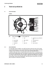
The division of the brake circuits is done using a two-part armature disk (2) with the respectively allocated
compression springs (1.2) and electromagnetic coils (8). Each brake circuit can be operated individually due
to the separate supply lines for each coil group and armature disk segment (
a microswitch (16) which monitors the switching state of the spring-applied brake. Using the associated
switching device, the supply voltage (AC voltage) is rectified and, when the brake is released, lowered after
a short period of time. This results in a reduction of the average electrical power of the brake.
The stator (1) is supplied in heat class F. The limit temperature of the coils (8) is 155 °C. The BFK464 spring-
applied brake is designed for a maximum operating time of 60 % with holding current reduction.
Certificate
3.1.2
Braking
During the braking procedure, the pressure springs (1.2) use the armature plate (2) to press the rotor (3)
(which can be shifted axially on the hub (4)) against the friction surface. The asbestos-free friction linings
ensure high braking torque and low wear. The braking torque is transmitted between the hub (4) and the rotor
(3) via gear teeth.
3.1.3
Brake release
When the brakes are applied, an air gap "s
L
" is present between the stator (1) and the armature plate seg-
ment (1). To release the brake, the coils (8) of the existing magnetic circuit are supplied with the correct DC
voltage. The resulting magnetic force works against the spring force to draw the armature plate segments
(1) to the stator (7). This releases the rotor (3) from the spring force and allows it to rotate freely
3.1.4
Release monitoring
The spring-activated brake has a microswitch (16) for each braking circuit to monitor the switching state.
When the brake is released, the microswitches (16) toggle. This means that it is possible to exclude the drive
being operated when the brake is closed. The microswitches can be connected as both normally open and
also normally closed.
To check that the microswitches function correctly, we recommend testing the switching status (refer to table
6) in both the released and applied braking states.
Type
EC-type examination certificate
Directive 95/16/EC
UCM
Directive 2014/33 EU
BFK464-17
S
ABV 948/1
ESV 948/1
EU-BD 948
BFK464-18
S
ABV 862/1
ESV 862/1
EU-BD 862
BFK464-18
S.2
ABV 903/1
ESV 903/1
EU-BD 862
BFK464-19
S
ABV 863/1
ESV 863/1
EU-BD 863
BFK464-20
S
ABV 849/1
ESV 849/1
EU-BD 849
BFK464-20
S.1
ABV 850/1
ESV 850/1
EU-BD 849
BFK464-22
S
ABV 975/1
ESV 975/1
EU-BD 975
BFK464-25
S
ABV 851/1
ESV 851/1
EU-BD 851
BFK464-25
S.1
ABV 869/1
ESV 869/1
EU-BD 851
BFK464-28
S
ABV 859/1
ESV 859/1
EU-BD 859
Summary of Contents for WSG-TB.3 series
Page 29: ......
Page 30: ......
Page 31: ......
Page 33: ......
Page 37: ......
Page 38: ......
Page 39: ......
Page 43: ......
Page 44: ......
Page 45: ......
Page 46: ......
Page 47: ......
Page 95: ...Notes INTORQ BA 14 0197 04 2016 48 Notes...
Page 144: ...Notes INTORQ BA 14 0210 12 2016 48 Notes...
Page 145: ...Notes INTORQ BA 14 0210 12 2016 49...
Page 146: ...Notes INTORQ BA 14 0210 12 2016 50...
Page 147: ......


