Mechanical installation
INTORQ | BA 14.0210 | 12/2016
27
4.4.5
Cover ring assembly
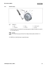
Fig. 11
Cover ring assembly
1. Pull the cable through the cover ring (13).
2. Push the cover ring (13) over the complete stator (1).
3. Press the lips of the cover ring (13) into the grove of the complete stator (1) and flange (6) or the bearing
shield.
DANGER
The brake may fail.
If the manual release is not adjusted correctly the brake may fail.
Possible consequences:
❚
Severe injuries or material damage.
Protective measure:
❚
Ensure that the dimension "s" is observed.
NOTICE
Brakes without flange require a groove in the bearing shield for the lip of the cover ring.
1
Stator, complete
6
Flange
13 Cover ring
2
Armature plate
10 Cylinder head bolt
NOTICE
Cover ring with condensation drain hole:
Attach the cover ring so that condensation can drain through the hole.
Summary of Contents for WSG-TB.3 series
Page 29: ......
Page 30: ......
Page 31: ......
Page 33: ......
Page 37: ......
Page 38: ......
Page 39: ......
Page 43: ......
Page 44: ......
Page 45: ......
Page 46: ......
Page 47: ......
Page 95: ...Notes INTORQ BA 14 0197 04 2016 48 Notes...
Page 144: ...Notes INTORQ BA 14 0210 12 2016 48 Notes...
Page 145: ...Notes INTORQ BA 14 0210 12 2016 49...
Page 146: ...Notes INTORQ BA 14 0210 12 2016 50...
Page 147: ......


