


rev02
MRK950-MRK960 Manager
Pag. 4
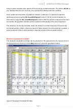
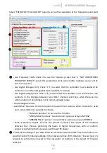
ON THE LEFT
a tree-structured view gives the ability to easily understand the structure and
composition of the connected systems. In fact, for every different connection to the PC (IP
address or USB post), in the manager is associated a main system, where single receivers or
accessories (accessible through the single connection) are leafs associated to the respective
main node. In the tree-view the main systems are shown as root nodes, while single receivers
are leafs. To every system is associated a different color (chosen from a list in the
configuration file), that allows easy recognition of the parent system of every single receiver
graphical module.
Selecting a single node and pressing the right button of the mouse, a popup menu appears,
showing a list of actions possible with the selected item.
ON THE RIGHT
are visualized the graphical modules of the receivers, of the racks and of the
accessories connected. Every module can be moved using a single drag-and-drop operation
inside the blue-gray panel. The position of the modules is “snapped” along an invisible grid, to
easily maintain the visualization panel in order. The height of every row of modules can be
reduced or pulled back to normal condition, using the small button at the bottom-right of any
module, in order to increase the number modules that can be visualized on the screen at the
same time.