WisyCom MRK950 Manual Download Page 14

rev02 

MRK950-MRK960 Manager


Pag. 

13 


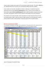
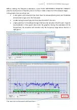
Intermodulation calculator 

With  Wisycom  Manager  it’s  possible  to  make  a  frequency  plan  calculation  intermodulations 
free.  To  do  this,  select  a  receiver  in  the  tree-structured  view  on  the  left  and  select 
Management>Intermodulation Calculator menu. 


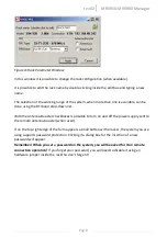
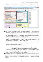
First  is  displayed  the  frequency  range  menu  where  it’s  possible  to  set  up  the  desiderate 
frequency range of calculation and the forbidden ranges if present. 

In  “WORKING  PPARAMETERS”,  the  receiver  working  range  and  the  frequency  step 
(25/50/100/200  KHz)  can  be  changed  (select  Custom  Range  to  change  the  receiver  working 
range and APPLY to confirm).  

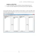
In  “SELECT  FREQUENCY  RANGES”  there  are  three  possibility    to  set  up  the  allowed  and 
forbidden frequency range: 

  changing the Start/Stop frequency of calculation 

  selecting the band of the Wisycom transmitters in the list 

  choosing the DVB-T channel (depending on the country) 

Select “Allowed range” or “Forbidden range” to add the range on the right table: 


if a range is allowed, the relative cell on the first column “#” become dark green. 


if a range is forbidden, the relative cell on the first column “#” become brown/red. 

In  the  section  below,  there  is  the  “Local  Region  Settings”  where  it’s  possible  load  a  specific 
configuration depending on the working area (there are two list box: Region and Area). 
It’s possible to create other new Region and Area: 


set the allowed and forbidden ranges 


save the configuration on the pc 


go  to  C:\Users\

User  that  had  install  the  Wisycom  Manager

\

AppData

\Roaming\ 

Wisycom\Rack Rx Manager (MRK9xx)\1.1.4.5\data\FrequencyRanges   

❶ 

❷ 

❸ 

Summary of Contents for MRK950

Page 1: ...MRK950 MRK960 Manager Products MRK950 options L H I M MRK950 EX options W X and MRK960 Rev rev02 ref Wisycom Manager 2010 v1 1 4 6 Date 23 July 2014...

Page 2: ...ction Basic Operation First start On the first startup if no Wisycom USB device is connected to the PC the software asks if you want to enable it in demo mode or if you want to search all the remote c...

Page 3: ...ssible to access the IP configuration window by clicking on the small gray icon on the right When the configuration is done the user can choose which network devices include on the management with the...

Page 4: ...onfiguration of a system without rendering it immediately active In this way it is possible to prepare an alternative to the actual configuration that can be saved on file and reloaded in a second tim...

Page 5: ...at allows easy recognition of the parent system of every single receiver graphical module Selecting a single node and pressing the right button of the mouse a popup menu appears showing a list of acti...

Page 6: ...rev02 MRK950 MRK960 Manager Pag 5 Figure 2 Main window example with two fully populated systems connected...

Page 7: ...unction after the system components has been connected the graphical modules will be replaced automatically in the same disposition The status bar on the main window shows the status of command queues...

Page 8: ...d frequency is outside the frequency range of the system i e using an MRK920 receiver the frequency is outside the current RF band of the RFI module To change working parameters of one or more receive...

Page 9: ...down list With the Antenna Booster checkboxes is possible to turn on and off the power supply sent to the remote antenna booster when used If on the top right edge of the form appears a small button w...

Page 10: ...resence of not enough covered locations and the effectiveness of the diversity system Enable RF A and RF B checkboxes to show Antenna A and Antenna B analysis In normal condition after the duration ti...

Page 11: ...his analysis is very useful when it is necessary to choose a new frequency allocation or to choose the best frequency for a radio link Enable RF A and RF B checkboxes to show Antenna A and Antenna B a...

Page 12: ...uency for a radio link Values measured in different instants in a cyclical way are plotted in a 3D graph allowing the user to understand precisely the variations of the signal levels in the time It is...

Page 13: ...ee view and start the 2D Spectrum Scanner analysis from the popup menu or from Tool 2D Spectrum Analyzer on the main menu Select the desired Frequency range the Step 100 200 500 KHz 1 2MHz and the Dat...

Page 14: ...to set up the allowed and forbidden frequency range changing the Start Stop frequency of calculation selecting the band of the Wisycom transmitters in the list choosing the DVB T channel depending on...

Page 15: ...requencyRanges and open it to insert a new area configuration save here the previous saved configuration If some single frequencies must be imposed as fixed solutions or must be avoided select DESIDER...

Page 16: ...wn red bar that show the allowed dark green and forbidden brown red ranges set in the first panel an alternating blue and grey bar that show the DVB T channels a light green bar in the allowed ranges...

Page 17: ...in the remain allowed range Skip Analogue Carriers Avoid Mixer Spurious this list box permit to avoid mixer spurious when a receiver is used near a transmitter It s possible to choose No Mixer Spuriou...

Page 18: ...ction Level list box where it s possible to set one of the four preloaded protection configurations High Medium Low or Low 2TX Only or the Custom configuration only with Custom it s possible to change...

Page 19: ...ck Draw Results under the graphic It s possible to zoom the graphic simply selecting the desiderate Setup Copy Import Export The user can easily copy import export the whole configuration of the conne...

Page 20: ...s Both receivers and systems can be used as source and destination with the difference that if a receiver is selected the data copy will affect just the selected receiver itself but if a whole system...

Page 21: ...ave to name properly all rack sets using the rack parameters windows ie first 4 MRK950 rack in main studio named main 2 MRK950 rack in the lobby named lobby Once again for each rack this name is assoc...

Page 22: ...the main menu in File Save Scene Figure 10 Load scene dialog box On load frequency data pop up menu us can chose among no frequency data loading for each receiver current group and channel along with...

Page 23: ...ode This mode is loading all frequency information for each receiver beware that is the system is big you are saving a lot of data 2000 frequencies for each receiver On Receiver data box us can chose...

Page 24: ...raphs that appear on this software You can also change the sequence of the colors that will be assigned in incremental way to the remote systems About graphical parameters of the movable graphical pan...

Page 25: ...toring from other PCs available from Wisycom Manger version 1 1 4 0 In the Master Slave configuration only one PC works as Master and can change the configuration of the receiver the other PCs work as...

Page 26: ...rver and pushing the show button it is possible to verify the IPs of the Master PCs The icon on the left panel has different shape which identify the type of connection rectangle for Master PC oval fo...

Page 27: ...cific model and firmware version Wisycom Manager Version Supported Wisycom Device Model Firmware Version 1 1 3 4 MRK950 MRK950EX 1 0 1 x 1 1 2 11 MRK960 1 1 0 x 1 1 2 0 MRK960 1 0 0 x 1 1 1 16 MRK950...

Reviews: