


Assembly and Operating Instructions
– Industrial sectional door MakroPro 100
,
MakroPro Alu 100
4
EN
IIiO/BS/MakroPro100/10/2015/ID-92974
+
Technical description
[B000004]
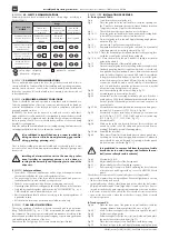
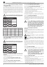
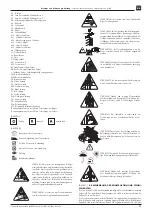
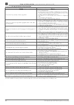
4.2. SAFETY RECOMMENDATIONS
Minimum protection levels provided in the door closing edge, according to
PN-EN 13241-1.
Door operation
method
Usage
Trained door
operators (private
premises)
Trained door
operators (public
premises)
Non-trained
door operators
(public premises)
Deadman control with
the view of the door
(Totmann version)
Push-button control
without electric
latching
Key-switch
control without
electric latching
Unacceptable
Impulse control with the
view of the door (Au-
tomatik version)
Impulse control without
the view of the door
(Automatik version)
Automatic control
(Automatik version –
automatic closing)
–
safety edge – obligatory
–
photocells – obligatory
–
photocells – optional
[A000005]
5. ASSEMBLY RECOMMENDATIONS
Prior to assemble and operate the door, the guidelines contained in this in-
struction should be read carefully. All assembling and operating instructions
must be strictly observed. It ensures the correct assembly, and durable and
failure-free operation. All works related to door assembly must be carried out
in described order.
[A000006]
6. REQUIRED ASSEMBLY CONDITIONS
The door should be used and operated in compliance with its intended use.
Selection and application of doors in construction industry should be based on
technical documentation of the facility developed in compliance with regula-
tions and standards in force.
[B000005] The doors can be mounted to reinforced concrete walls, those
made of bricks, or steel frameworks. A room intended to mount the doors should
be finished completely (plastered walls, finished floor), walls must not have any
faults in quality of work. The room should be dry and free of chemicals being
harmful for coating paints.
Both side walls, and frontal wall and door assembly opening lintel must be verti-
cal and perpendicular to the floor, and must be finished.
It is prohibited to install the door in a room in which fin-
ishing works are still to be done (plastering, gypsum fin-
ishing, grinding, painting, etc.).
Floor in bottom sealing area must be levelled and constructed in such a way
as to ensure free water drain. Appropriate ventilation (drying) of garage must
be ensured.
Installing of electrical drive unit to the door by profes-
sional installer or competent person is to be done ac-
cording to the Assembly and Operating Instruction of the
drive unit.
[B000009]
Safety conditions
• The methods of electrical installation as well as its protection against electric
shock are described by the norms and regulations in force.
• The power supply circuit of the drive should be equipped with power cut,
residual-current device and overload circuit protection.
• The door power supply should be done as a separate power circuit.
• Grounding of the drive unit is obligatory and should be done in the first place.
• Only cables supplied together with the drive by “WIŚNIOWSKI” Sp. z o.o.
S.K.A. should be used to assemble the drive unit.
• Electrical installation should be done according to the acting regulations of
a particular country.
• All electrical works must be performed by certified installer only.
[D000001]
7. ASSEMBLY INSTRUCTION
The correct operation of the door is closely connected with its proper assem-
bling. “WIŚNIOWSKI” Sp. z o.o. S.K.A. recommends the authorized assem-
bly companies. Only the proper assembly and maintenance according to the
Instruction and provided by the competent company or person may guarantee
safe and designated operation of the door.
Please keep the list of garage door’s component parts (specification).
[D000035]
7.1. INSTALLATION PROCEDURE:
A. Track system STL-HL:
Fig. 8.
Screw bracket to vertical guide rails.
Fig. 9.
Place the guide rail to the wall and face it with the opening. Use
the C-profile to determine the exact distance between brackets.
Temporally screw the C-profile to both brackets.
Fig. 7.
Check the distance between brackets acc. to the figure.
Fig. 10-13. Move the guide rail and bracket aside, and make mounting holes
in a wall. Place the anchor sleeves into these holes.
Fig. 12-13. Fix vertical guide rails to the wall. Apply fastening angle plate as
an option (Fig. 14).
Fig. 15.
Unscrew the C-profile connecting the brackets.
Fig. 15.3. Dismantle brackets from vertical guide rails, and fix it (movable)
with clamp plates to horizontal guide rails (fig. 16).
Fig. 16.5-16.7. Place the horizontal guide rail and bracket to the opening, face
it with the vertical guide rail and fasten with bolts.
Fig. 16.9-16.11. Place the bracket to the wall, and bolt it tightly to horizontal
guide rails and wall.
Fig. 17.
Check the diagonals of the installed guide rails.
Fig. 18.
Fix the horizontal guide rails to the ceiling with mounting brackets.
Standard mounting brackets supplied with the door should only
be applied when the maximum distance between the horizontal
guide rail and ceiling does not exceed 380 [mm]. It is prohibited
to lengthen the brackets. When it is required to mount the guide
rails at the distance of more than 380 [mm] from the ceiling, frame
construction should be used to ensure stability of the horizontal
rails. It is prohibited to mount the guide rails in such a way that
allows its moving during the door operation.
Fig. 22.
Level the horizontal guide rails according to fig. 5.1.
Fig. 23.
Mount bumpers to horizontal guide rails.
Fig. 25.
Mount the C-profile connecting horizontal guide rails. If the door
width is above 5000 [mm], additional brackets should be used to
fix the C-profile of horizontal guide rails in at least one place, at
equal intervals.
Fig. 27-29. Mount the drive shaft, and lubricate the bearings with base grease
(actuator SI 55, actuator SI 17,SI 25,SI 40 - fig. 34).
Fig. 30.
Mount the door drive: install a key to a keyway, mount an actua-
tor (SI 55, fig. 35 - SI 17, SI 25, SI 40), and secure it with a ring
(SI 55 - fig. 33, SI 17, SI 25, SI 40 - fig. 37).
Fig. 41.
Mount the cable.
Fig. 38.
Wind up the cable on a drum (when two/ three revolutions are
wound up, cut the rest of the cable and protect its end from un-
winding). Bolt tightly the cable fastening plates.
Fig. 39-48. Assemble the door leaf.
Fig. 42.
Place about 2 [mm] thick cardboard pieces between panels near
each hinge to ensure the proper gap between panels. Cardboard
pieces should be removed during door opening, when the panels
are bent towards each other (fig. 51.1).
It is prohibited to remove foil from the cutter of cable
break device to avoid damages and facilitate the con-
trol (in case safety break is activate).
Fig. 49.
Mount a bolt/ lock.
Fig. 50.
Adjust initially the roller of the first segment.
Fig. 51.1.
Adjust initially the roller of remaining segments.
Fig. 51.
Door opening/ closing tests. Before operating the door, lubricate
rollers, bumpers and hinges with e.g. semi-solid HWS-100 Wurth
grease.
Check the correct operation of electrical safety devices (if applicable):
• photocells - simulate the working conditions. When the light beam is crossed,
the door should stop and reverse,
• optical safety edge - the door should stop and reverse, when the leaf touches
80 [mm] in diameter and 50 [mm] high object located on the floor. If neces-
sary, adjust and check again. Improper adjustment may cause an accident.
• lock sensor - when the lock is closed, the door should not start its operation,
• open wicket door sensor - when the wicket door is open, the door should
not start its operation.
B. Track system VL:
Fig. 68.
Place the lower part of the guide rail to wall and face it with the
opening - distance between rails should be acc. to fig. 67.
Fig. 68.1. Mark out the mounting holes (for the lower rail part) on the wall.
Fig. 69.
Put the lower rail part aside.
Fig. 70.
Drill mounting holes (for the lower rail part) in the wall, and place
the anchor sleeves into these holes (fig. 71).
Fig. 72.
Place the lower rail part to wall and face it with the opening.
Fig. 73.
Fix lower rail part to the wall. Apply fastening angle plate as an


