background image

Assembly and Operating Instructions

 – Industrial sectional door MakroPro 100 

,

 MakroPro Alu 100

2

EN

IIiO/BS/MakroPro100/10/2015/ID-92974 

+

 Technical description

TABLE OF CONTENTS:

1.   General information ........................................................................................ 2
2.  Terms and definitions acc. to standard .......................................................... 2
3.   Definition of symbols ....................................................................................... 2
4.   Design description and technical data .......................................................... 3
 

4.1.   Application and designation ................................................................ 3


4.2.  Safety recommendations ...................................................................... 4

5.  Assembly recommendations ........................................................................... 4
6.   Required assembly conditions ........................................................................ 4
7.   Assembly instruction ........................................................................................ 4
 

7.1.   Installation procedure ............................................................................ 4


7.2.   Installation of safety device against door prising ................................ 5


7.3.  Lock and wicket door limit switch installation ....................................... 5


7.4.  Circuit diagram for key switch ............................................................... 5


7.5.   Circuit diagram for light curtain ............................................................ 5


7.6.   Circiut diagram for signal lights ............................................................ 5


7.7.   Circuit diagram for photocells ............................................................... 5


7.8.  Assembly of the shield for IP-65 control panel ..................................... 5


7.9.  Cable laying for IP-54 control panel .................................................... 5


7.10. Circuit diagram for eL A1 ..................................................................... 5


7.11.  Circuit diagram for leading photocells (two channel system) ............. 6


7.12. Circuit diagram for leading photocells (one channel system) ............ 6


7.13. Installation of bumper plate for leading photocells ............................. 6


7.14. Circuit diagram for warning light .......................................................... 6


7.15. Installation of spiral cable holder ......................................................... 6


7.16. Installing the padlock holder ................................................................. 6


7.17.  Faults during door installation ............................................................... 6

8.   Additional requirements ................................................................................. 6
9.   Environmental protection ................................................................................ 6
10.  Door disassembly ............................................................................................ 6
11.  Operating remarks .......................................................................................... 6
12.  The range of environmental conditions, for which the door 
 

has been designed .......................................................................................... 7

13.  Door operating instruction .............................................................................. 7
14.  Routine maintenance instruction ..................................................................... 8
15.  Restraints in door operation ............................................................................ 8
16.  Frequently asked questions ............................................................................ 9

[A000001] 

1. GENERAL INFORMATION 

The door can be installed and adjusted by at least a COMPETENT person.
[B000001] The door is insulated, and is designed to be installed from inside 
the premises.
[B000092] The area to install the door should be free from any pipes, cables, etc.
[A000002] The present Instruction is a document intended for Professional In-
stallers or Competent persons. It contains necessary information to ensure safe 
installation of the door.
The door and its separate parts should be installed according to Assembly and 
Operating Instruction provided by “WIŚNIOWSKI” Sp. z o.o. S.K.A. 
Only original fittings supplied together with the door must be used to install the 
door.
Please be familiar with all instructions prior to start with assembly. Please read 
carefully the present instruction and follow its recommendations. The correct op-
eration of the door depends from its proper installation to a considerable extend.

The Instruction includes the assembly of the door with standard 

equipment and optional equipment elements. The scope of stand-

ard and optional equipment is described in sales offer.

[B000024] The door packaging is intended solely to secure the door during 
transportation. 
Packaged doors must not be exposed to adverse impact of weather conditions. 
They must be stored on hardened, dry surface (flat level surface which does not 
change its properties under internal factors), in enclosed, dry and airy rooms, in 
the place where they will not be exposed to any other external factors that may 
cause deterioration of stored doors, components and packaging. It is forbidden 
to store and warehouse the doors in wet rooms and rooms with fumes harmful 
for painted and zinc plated coatings.
[B000025] Airtight foil packaging must be unsealed when storing the doors to 
avoid adverse change of microclimate inside the packaging, which can result in 
the damage of painted and zinc plated coating.
[B000002] The selection of fastening elements is determined by the type and 
structure of the construction material to which the door will be fastened essen-
tially. Nail expansion anchors supplied with the door normally are designed to 
anchor in solid materials with compacted structure (e.g. concrete, solid brick). 
If  the  doors  are  mounted  to  another  materials,  it  is  necessary  to  change  the 
fastening elements for that ones suitable for anchoring in the materials of which 
the walls and ceiling are made. For this purpose, the installer must follow the 
guidelines for selection of fastening elements supplied by their manufacturer.
[B000028] Glasses used in glazed elements (windows, aluminium glazed pro-

files) are made of plastic. The absorbency of moisture from the air is the natural 
property of plastic glasses, which in changing weather conditions can result in 
temporary steam precipitation and settlement inside the glass. Sweating of glazed 
aluminium profiles is a natural phenomenon, and is not subject to warranty claims. 
[C000094] Aluminium profiles used in the doors are made of profiles without 
thermal barrier. Sweating of aluminium profiles is a natural process and it shall 
not be subject to claims. 
[A000003] The Instruction applies to several types of doors. Reference draw-
ings may vary in execution details. If it is essential, these details are shown in 
separate drawings. 
The Instruction contains all essential information that guarantees safe assembly, 
operation and proper maintenance of the door.
During the assembly all Health and Safety regulations pertaining to assembly 
and cutting operations as well as power tools, depending on methods of assem-
bly must be strictly observed, considering the norms, regulations and applicable 
building process documentation. 
During repair works, the door must be protected against plaster, cement and 
gypsum which may cause stains.
Assembly and Operating Instruction is a document intended for the door own-
er. Once the assembly works are completed, the instruction should be handed 
over to the owner. The instruction is to be kept in a safe place and protected 
against damage.
If elements supplied by the third party manufacturers and suppliers are used 
during  the  assembly,  the  person  assembling  the  door  is  considered  to  be  its 
producer according to EN 13241-1.
Tampering and removing of any door parts is strictly prohibited. It may result 
in the elements responsible for safe operation being damaged. Unauthorized 
replacing of door sub-assemblies is strictly prohibited. 
[A000042]  When  installing  a  drive,  recommendations  of  “WIŚNIOWSKI” 
Sp.  z  o.o.  S.K.A.,  manufacturer  of  drive  and  auxiliary  equipment  should  be 
observed. Only original elements supplied by the manufacturer should be used 
to connect the drive.
[A000051]  It  is  not  allowed  to  make  any  modifications  (e.g.,  shortening)  of 
sealing used in door.
[B000003] It is prohibited to obstruct the door movement area. The door opens 
vertically upwards. Therefore, no obstacles may be located in the way of door 
opening  or  closing.  It  is  necessary  to  ensure  that  during  door  movement  no 
persons, especially children, or objects are on its way.

[A000037] 

2. TERMS AND DEFINITIONS ACC. TO STANDARD

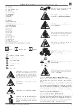
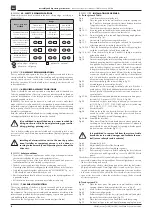
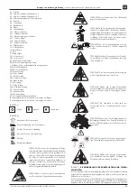
Explanation of warning signs used in the Instruction:

Attention!

 - warning sign used to denote the attention.

Information

 - warning sign used to denote important information.

Reference mark

 - sign referring to a given paragraph in the As-

sembly Instruction.

Professional Installer 

- competent person or organization, offering to third 

parties door installation services, including its improvement (according to EN 
12635).

Competent person

 - an appropriately trained person with qualification re-

sulting from knowledge and practical experience, and provided with necessary 
instruction  to  enable  the  required  installation  to  be  carried  out  correctly  and 
safely (acc. to EN 12635).

Owner

 - a natural or legal person who has legal title to administer the door, 

and takes responsibility for its operation and use (acc. to EN 12635). 

Report Book

 - a book containing the main data about the door, and which 

has a specially designated places for records about inspections, tests, mainte-
nance and various repairing works or modifications to the door (according to 
EN 12635).

[D000009] 

3. DEFINITION OF SYMBOLS

The numbers on Fig. 1 refer directly to the figure numbers stated in the following 
Instruction. 
A1 - door leaf 


A2 - set of vertical guide L  


Sz - ordering width
A3 - set of vertical guide P 


A4 - connector of guide rails 


A5 - bracket 


A6 - cable drum  


A7 - drive shaft 


A8 - mounting bracket
A9 - side sealing 


Summary of Contents for MakroPro 100

Page 1: ...PART 1 EU 1 2 page 19 CS Technický popis Návod k instalaci a obsluze Průmyslová sekční vrata MakroPro 100 MakroPro Alu 100 ČÁST 2 Technická dokumentace přejděte na ČÁST 1 EU 1 2 strana 37 SK Technický popis Návod na montáž a obsluhu Priemyselná segmentová brána MakroPro 100 MakroPro Alu 100 ČÁST 2 Technická dokumentácia prejdite na ČASŤ 1 EU 1 2 strana 45 RU Техническое описание Инструкция по монт...

Page 2: ...or anchoring in the materials of which the walls and ceiling are made For this purpose the installer must follow the guidelines for selection of fastening elements supplied by their manufacturer B000028 Glasses used in glazed elements windows aluminium glazed pro files are made of plastic The absorbency of moisture from the air is the natural property of plastic glasses which in changing weather c...

Page 3: ...ove the protective film from the door sheet metal skin immediately after installation C000389 Do not remove or modify any compo nent of the garage door C000390 Keep your hands and all objects clear from the working range of all moving components of the door and the door latch lock and guides C000391 Remove the protective film from the glazing immediately after installation C000392 Removing the pan...

Page 4: ...mine the exact distance between brackets Temporally screw the C profile to both brackets Fig 7 Check the distance between brackets acc to the figure Fig 10 13 Move the guide rail and bracket aside and make mounting holes in a wall Place the anchor sleeves into these holes Fig 12 13 Fix vertical guide rails to the wall Apply fastening angle plate as an option Fig 14 Fig 15 Unscrew the C profile con...

Page 5: ...e door screw it under the lock rod Connect the cables to the terminals 21 and 22 of the limit switch Fig 122 Lay the cables along the door leaf to the terminal box Fig 125 2 Open the optical edge terminal box mounted on the door leaf Remove the bridge from the terminals in the box as shown on the figure Connect the cables of lock and or wicket door limit switch in the place of the removed bridge a...

Page 6: ...may lead to troubles in door operation door damage or as a result provide to the loss of the warranty A000007 8 ADDITIONAL REQUIREMENTS After the installation is completed it must be checked that the door is fitted with CE data plate according to the standard If this plate is missing fit the door with such a data plate After verifying the correct operation of the door the Assembly and Operating In...

Page 7: ...oor operation in normal conditions without power shut down without electrical latching the opening closing door should be observed by the operator 1 Opening press and hold the button up till the door is fully open 2 Closing press and hold the button down till the door is fully closed 3 To stop the door in any position release the button II Door operation in normal conditions without power shut dow...

Page 8: ...ing clear height In doors with an electrical drive check the operation of electrical safety de vices if applicable once in a month photocells simulate the work conditions situation For this purpose cross the light beam the door should stop and return to its previous position optical safety edge the door should stop and reverse when the leaf touches 80 mm in diameter and 50 mm high object located o...

Page 9: ...heck the cables for proper winding up and tension Check cables length Rollers slipped out from the guide rail Check the proper adjustment of the limit switch Check the distance between the guide rails Check the guide rails for any deformations Automatic door does not stop when it encounters an obstacle Check safety edge operation Check the condition and proper connection of spiral cable Check the ...

Page 10: ...enen Wand und Deckenbaustoffen bestimmt worden sind Zu diesem Zweck muss der Monteur die Richtlinien zur Auswahl der Befestigungselemente beachten die durch deren Hersteller geliefert wurden B000028 Die in den Verglasungen eingesetzten Scheiben Fensterchen ver glaste Alu Profile werden aus Kunststoff hergestellt Eine natürliche Eigenschaft der Kunststoffscheiben ist Absorption der Luftfeuchte was ...

Page 11: ...n Ferner dürfen dort weder Fahrzeuge noch andere Gegenstände abgestellt werden C000384 Es ist verboten das Tor zum Anheben von Personen oder Gegenständen anzuwenden C000385 Es ist verboten ein nicht voll funktionsfä higes Tor anzuwenden C000386 Alle Durchsichten und Wartungsarbei ten am Tor sind gemäß der Bedienungs und War tungsanleitung durchzuführen Vor und während der Tor Inbetriebnahme sind a...

Page 12: ...ll Der Antriebsversorgungskreis soll mit einer Spannungssperre einem Strom vergleichsschutz und einem Überstromschutz ausgerüstet werden Die Installation zur Torversorgung soll als ein getrennter elektrischen Kreis realisiert werden Die pflichtmäßige Erdung des Antriebs soll in erster Reihe hergestellt werden Zur Montage sollen die durch die Firma WIŚNIOWSKI Sp z o o S K A mit dem Antrieb geliefer...

Page 13: ...le nach dem Ansprechen der Bremse erleichtert wird darf das Band von dem Messer an der Absicherung gegen Seilbruch nicht entfernt werden Abb 116 Den Riegel das Schloss montieren Abb 117 Den Wälzzylinder des ersten Segments voreinstellen Abb 117 1 Den Wälzzylinder der übrigen Segmente voreinstellen Abb 118 Den Anschlag im oberen Teil der Führungsleiste montieren Abb 119 Das Torheben und senken ausp...

Page 14: ...gangstür an die Steuerung WS 900 Es soll die Brücke A entfernt werden Die Klemmen ST ST beziehen sich auf den Anschluss der Spiralleitung Die Arbeitskontakte dürfen mit dem Strom 5 A 24 V belastet werden Der fehlerhafte Anschluss des Systems hat das Durchbrennen der Sicherung in der Steuerung WS 900 zur Folge Das Anschlussschema befindet sich in der Abb 150 D000383 7 11 ANSCHLUSSPLAN FOTOZELLEN ZW...

Page 15: ...iten im Raum soll das Tor vor den Putzsplittern Farben und Lösungsmitteln gesichert werden die elektrisch gesteuerten Tore sollen gemäß der zusammen mit der Elektro ausrüstung gelieferten Anweisung aufgemacht werden sollten beim Toranheben übermäßige Widerstände auftreten muss man prü fen ob die Scharniere vorschriftsmäßig eingestellt worden sind Bei eventu ellen Inkorrektheiten soll eine Nachstel...

Page 16: ...1 Handarbeit maximale Betätigungskraft 50N Die Steuerungsspannung ist unterbrochen und es ist unmöglich das Tor elektrisch zu bewegen Das Tor kann mit der Zapfkette auf und zugemacht werden 2 An dem grünen Griff der aktivierenden Kette leicht bis zum Anschlag ziehen 3 elektrische Arbeit maximale Betätigungskraft 50N Die Steuerungs spannung ist wiederholt eingeschaltet und es ist möglich das Tor el...

Page 17: ...h leis tungsfähig sind Sollten Fehler in der Arbeit der elektrischen Antriebe festgestellt werden müssen diese von der elektrischen Spannung für 2 3 Minuten abgeschaltet und erneut eingeschaltet werden die Einstellung der Wälzzylinder kontrollieren im Bedarfsfall nachstellen den Zustand der Durchgangstür überprüfen im Bedarfsfall nachstellen sollten irgendwelche Fehler festgestellt werden müssen d...

Page 18: ...g auf die Trommel aufgespult Prüfen ob die Seile korrekt aufgespult und aufgespannt sind Die Seillänge kontrollieren Die Wälzzylinder sind aus der Führungsleiste ausgefallen Bei automatischen Toren die Einstellung des Endlagenbegrenzers kontrollieren Den Abstand der Führungsleisten überprüfen Den Zustand der Führungsleisten auf Verformungen prüfen Das automatische Tor hält nicht an wenn es auf ein...

Page 19: ...aux matériaux durs béton brique pleine etc En cas d autre type de matériau il est nécessaire de choisir des pièces de fixation adap tées aux matériaux des murs et du plafond Pour ce faire l installateur devrait se servir des conseils fournis par le fabricant de pièces de fixation B000028 Les vitrages employés dans les éléments vitrés hublots profils vitrés en aluminium sont faits en matière plasti...

Page 20: ...tail C000390 Il est interdit de placer les mains ou des objets dans la zone de fonctionnement des éléments mobiles du portail ou dans la zone de fonctionne ment du verrou de la serrure ou des guidages du portail C000391 Après le montage du portail il faut di rectement retirer le film de protection de la surface de la verrière C000392 Méthode de sortie des panneaux du colis Ne pas jeter de boulons ...

Page 21: ...moyen d un profilé d assemblage en U en le vissant provisoirement aux consoles Fig 7 Vérifier l emplacement des consoles avec le dessin Fig 10 à 13 Ecarter les rails de guidage et les consoles tracer les trous de montage sur le mur et enfoncer les chevilles de montage dans les trous forés Fig 12 à 13 Fixer les rails de guidage verticaux au mur Il est possible en op tion de monter un fer cornière d...

Page 22: ... de la porte Enlever le cavalier dans la boîte comme sur le dessin Connecter les fils à la place du cavalier enlevé et brancher les fils de la barre palpeuse si elle est installée La connection faite le vérin ne va fonctionner que lorsque le portillon est fermé concerne le disjoncteur de fermeture extérieur du portillon D000311 Mode de connection des disjoncteurs de fermeture de la serrure et du p...

Page 23: ...0 B000169 7 16 MONTAGE DE L ORIFICE DU CADENAS Le mode de montage de l orifice du cadenas au rideau tablier de la porte est illustré sur la fig 195 B000014 7 17 ERREURS DE MONTAGE DES PORTES Pour éviter le risque des erreurs qui pourraient être commises lors du montage de la porte veuillez faire attention à ce que les rails de guidage horizontaux soient correctement installés conformément aux disp...

Page 24: ...La différence entre la température externe environnante et interne à l intérieur de la pièce peut conduire à la flexion des éléments de la porte effet bilame Dans ce cas l activation de la porte peut entraîner son endommagement C000012 Avant la première ouverture de la porte vérifier l exac titude de son montage conformément au manuel d installation et d utilisation La porte est monté correctement...

Page 25: ... course contrôler en appuyant sur le bouton approprié haut bas sur l unité de contrôle et observer la butée de porte après l arrêt de la porte en position fermée les cordes doivent rester tendues l arrêt de la porte en position ouverte le joint inférieur ne doit pas descendre plus bas que le trou de lumière Pour les portes à l entraînement électrique une fois par mois vérifier le bon fonctionnemen...

Page 26: ...nroulées sur le tambour Vérifier l enroulement et la tension des cordes Vérifier la longueur des cordes Les galets sont sortis du rail de guidage Vérifier le réglage de l interrupteur de fin de course Vérifier l écartement des rails de guidage Vérifier l état des rails de guidage s ils ne sont pas déformés La porte motorisée ne s arrête pas sur l obstacle Vérifier le fonctionnement de la barre pal...

Page 27: ...твуют пары вредных для лакокрасочных и оцинкованных по верхностей веществ B000025 Во время складирования герметичная пленочная упаковка должна быть распечатана во избежание изменения микроклимата внутри упаковки что в результате может привести к ухудшению со стояния лакокрасочной и оцинкованной поверхности B000002 Вид и структура строительных материалов к которым будут крепиться ворота коренным об...

Page 28: ...выключатель WWK внутренний концевой выключатель Pb коричневый кабель Pg зелёный кабель Pw белый кабель Pbk чёрный кабель Pbl синий кабель Pr красный кабель Py жёлтый кабель Pyg желто зеленый кабель Pgr серый кабель Fw функция гашения Wp выход переключателя Wt тестовый вход не подключать номер рисунка a касается монтажа ворот с засовом номер рисунка b касается монтажа ворот с замком A000052 дополни...

Page 29: ...ке A000006 6 УСЛОВИЯ НЕОБХОДИМЫЕ ДЛЯ УСТАНОВКИ Ворота должны использоваться и эксплуатироваться по назначению Выбор и использование ворот в строительстве необходимо осущест влять на основании технической документации объекта подготов ленной в соответствии с действующими нормами и стандартами B000005 Ворота можно крепить к железобетонным и кирпичным стенам а также стальным рамам Помещение предназна...

Page 30: ...ть причиной несчастного случая датчик закрытия замка если замок находится в закрытом положе нии ворота не могут начать работать датчик закрытия проходной двери если проходные двери откры ты ворота не могут начать работать B Система направляющих VL Рис 68 Приставить нижнюю часть направляющей к стене и срав нять с проёмом расстояние между направляющими со гласно рис 67 Рис 68 1 Произвести разметку м...

Page 31: ...нно применяются концевые выключате ля проходных дверей и замка их подключение следует произвести последовательно в место снятого моста При условии правильного подключения привод будет рабо тать только если замок будет открыт а проходные двери закрыты D000314 7 4 СХЕМА ПОДКЛЮЧЕНИЯ ВЫКЛЮЧАТЕЛЯ С КЛЮЧОМ Подключение выключателя с ключом к приводу GfA с панелем управления TS 961 TS 970 TS 970AW TS 981 ...

Page 32: ...хнический паспорт B000013 После установки ворот следует немедленно удалить защитную пленку с обшивки створки Невы полнение этого требования может привести к очень сильному склеиванию плёнки с обшивкой под воз действием солнечных лучей Это не позволит откле ить плёнку и может привести к повреждению лако красочного покрытия обшивки Ворота с электроприводом необходимо открывать со гласноИнструкциипом...

Page 33: ...в результате раз ницы температур Разница наружной температуры окружающей среды и внутренней температуры помещения может привести к деформации элементов ворот биметаллический эффект Запуск ворот в такой ситуации может привести к их по вреждению C000012 Перед первым открытием ворот следует проверить правильность их установки в соответствии с Инструкцией по монтажу и эксплуатации Ворота установлены п...

Page 34: ... поврежденная проволока коррозия проверить все соединения а также их крепление особое внимание обратить на крепёжные болты направляющих и шурупы петельных соединений в случае обнаружения каких либо неисправностей провести их устранение проверить крепление привода проверить соединение шпонки с валом B000029 Для чистки элементов остекления окошек застекленных алюминиевых профилей следует использоват...

Page 35: ...стве несущей структуры здания в качестве герметической преграды A000011 Все работы выполнять в соответствии с данной Инстуркци ей по монтажу и эксплутации ворот Любые замечание и рекоменда ции необходимо довести до сведения владельца ворот в письменном виде например произвести соответствующую запись в техпаспорте или гарантийном талоне ворот и передать их владельцу После вы полнения техосмотра под...

Page 36: ...тросов на барабан Проверить правильность наматывания и натяжение тросов Проверить длину тросов Ролики выпали из направляющих Проверить правильность положения концевых выключателей Проверить расстояние между направляющими Проверить направляющие на наличие деформации Автоматические ворота не останавливаются в случае наезда на препят ствие Проверить работу оптических датчиков нижнего уплотнителя Пров...

Page 37: ...í k upevňování v materiálech z nichž jsou zhotoveny stěny a strop Za tímto účelem musí provádějící montáž použit výrobcem dodané směrnice pro volbu upevňovacích prvků B000028 Skla používaná v proskleních okénka prosklené hliníkové profily jsou zhotoveny z umělé hmoty Přírodní vlastnosti skel z umělých hmot je pohlco vání vlhkosti ze vzduchu což v proměnlivých povětrnostních podmínkách může způsobi...

Page 38: ...ed měty do míst kde pracují pohyblivé díly vrat a do míst kde pracuje západka zámek nebo vodicí lišty vrat C000391 Po montáži vrat ihned odstraňte ochrannou fólii ze skla C000392 Způsob vybalování panelů z balíku Nevyhazujte vruty upevňující panely je možné je využít pro přišroubování závěsů C000393 Zabalená vrata nesmějí být vystavena působení nepříznivých povětrnostních podmínek C000414 Je zakáz...

Page 39: ... vložky montážních kolíků ve vyvrtaných otvorech Obr 12 13 Upevnit svislé vodící lišty ke zdí jako volitelná možnost se může použit výztužný úhelník obr 14 Obr 15 Odšroubovat spínací profil U od konzol Obr 15 3 Demontovat konzoly ze svislých vodících lišt a namontovat po hyblivě pomoci montážních kostek na vodorovné vodící lišty obr 16 Obr 16 5 16 7 Přiložit vodorovnou vodící lištu spolu s konzolo...

Page 40: ...ést vodiče křídlem vrat ke spojovací krabici Obr 125 2 Otevřít spojovací krabici optické lišty montovanou na křídle vrata Odstranit kotvu ze svorek v krabici dle obrázku Zapojit vodiče koncového vypínače zámku a nebo průchozích dveří při sou časném použití koncových vypínačů průchozích dveří a zámku se musí tyto spojit sériově namísto odstraněné kotvy a napojit vodiče optické lišty pokud je namont...

Page 41: ...y A000007 8 DOPLŇUJÍCÍ POŽADAVKY Po ukončení instalace je třeba ověřit zda jsou vrata vybavená popisným štítkem CE v souladu s normou a v případě zjištění jejího nedostatku vybavit vrata po pisným štítkem Po ověření správnosti funkce vrat je třeba předat majiteli Návod k instalování a obsluze vrat a knihu vrat pokud se vyžaduje B000013 Po namontování vrat je třeba bezodkladně odstranit ochrannou f...

Page 42: ...lů a držet až k úplnému zavření vrat 3 Zastavení vrat v každé poloze mezitlačítkem je uvolněním tlačítka II Obsluha vrat za běžných podmínek bez zániku napájecího napětí se samoudržením během zavírání nebo otevírání se vrata musí nacházet v dosahu zraku operátora 1 Otevření jednou stisknout tlačítko nahoru a vyčkat až k úplnému otevře ní vrat 2 Zavírání jednou stisknout tlačítko dolů a vyčkat až k...

Page 43: ...t s elektrickým pohonem jednou za měsíc kontrolovat správnost funkce elektrických zabezpečení pokud jsou použity fotobuněk simulováním pracovních podmínek po skřížení se světelným paprskem se vrata musí zastavit a couvnout optické lišty vrata se musí zastavit a couvnout když křídlo narazí na předmět o průměru 80 mm ve výšce 50 mm umístěný na podlaze V případě potřeby nastavte a opět zkontrolujte č...

Page 44: ...it ochra nu za novou Lanka nesprávně navinutá na buben Kontrolovat správnost navinutí a natažení lanek Kontrolovat délku lanek Kladky vypadly z vodící lišty Kontrolovat správnost seřízení koncového dorazu Kontrolovat odstup vodících lišt Kontrolovat stav vodících lišt zda nejsou deformovány Automatická vrata se nezastavuje po najetí na překážku Kontrolovat funkci okrajové bezpečnostní lišty Kontro...

Page 45: ...ajúcich ele mentov na iné vhodné pre upínanie v takých materiáloch z akých sú vykonané steny a strop Za týmto účeľom osoba ktorá montuje bránu musí dodržiavať pokyny výberu upínajúcich elementov dodaných cez výrobcu B000028 Sklá používané v preskleneniach okienka hliníkové presklenené pro fily sú vykonané z umelej hmoty Prírodzenou vlastnosťou skiel z umelej hmoty je absorpcia vlhkosti zo vzduchu ...

Page 46: ...žite odstrániť ochrannú fóliu z plechu plášťa krídla C000389 Je zakázané odstraňovať prvky brány alebo zasahovať do ich konštrukcie C000390 Siahať rukami alebo inými predmet mi do pracovného priestoru pohyblivých prvkov brány a do pracovného priestoru závory zámku alebo vedení brány je zakázané C000391 Po namontovaní brány je potrebné okamžite odstrániť ochrannú fóliu z povrchu okna C000392 Spôsob...

Page 47: ...ch kolíkov nasadiť vo vyvrtaných otvoroch Nákres č 12 13 Zvislé vedenia upínať k stene ako opcia môže byť upevňujú ci uholník nák 14 Nákres 15 Spínajúcu oceľ odkrútiť od konzól Nákres 15 3 Odmontovať konzoly od zvislých vedení a namontovať ich po hyblivie pomocou montážnych kôstočiek k vodorovným vedeniam nák 16 Nákres č 16 5 16 7 Doložiť vodorovné vedenie spolu s konzolou k tvoru zrovnať so zvisl...

Page 48: ...zámky pod koncovky 21 ako aj 22 krajného vypínača zapnúť vodiče Nákres č 122 Vodiče previesť po krídle brány k pripájacej krabici Nákres č 125 2 Otvoriť pripájacú krabicu optickej lišty montowanej na krídle brány Odstrániť strmeň z upínadiel v krabici podľa nákresu Vopnúť ppripnúť vodiče krajného vypínača zámky alebo integro vaných dvier pri súčasnom použití krajných vypínačov integrova ných dverí...

Page 49: ...ulované podľa inštrukcie nárazníky boli stisnuté pri otvorenej bráne nákr 26 všetky spojené časti musia byť správne dotiahnuté Nedodržiavanie vyššie uvedených základných odporúčení môže spôsobiť problémy v správnom fungovaní brány poškodenie brány alebo stratu záruky A000007 8 DODATOČNÉ POŽIADAVKY Po skončení inštalácie treba overiť či brána má štítok CE v súlade s normou ak nie tak treba štítok z...

Page 50: ...je prípustné iba v prípade ked zám ka alebo západka sú v otvorenej polohe C000028 Brána s elektrickým polonom I Obsluha brány za normálnych podmienok bez zániku napá jajúceho napätia bez samouchytenia počas zatvárania ale bo otvárania brána musí byť v dosahu zraku operátora 1 Otváranie vtláčiť tlačidlo hore a držať k úplnému otvoreniu brány 2 Zatváranie vtláčiť tlačidlo dole a držať k úplnému zatv...

Page 51: ...iť cez vtláčenie príslušného tlačidla hore dole v riadenom ústredí a pozorovanie miesta zadržania brány po zadr žaní brány v zatvorenej polohe lanká majú zostať napnuté po zadržaní brá ny v otvorenej polohe dolná upchávka má vychádzať povyše otvoru svetla V bránach s elektrickým pohonom raz za mesiac overiť správnosť fungovania elektrických zabezpečení ked sú používané fotobuniek cez simulovanie p...

Page 52: ... na bubon Overiť správnosť navinutia alebo natiahnutia laniek Overiť ich dlžku Valčeky vypadli z vedenia Overiť správnosť regulácie koncovky otvárania Overiť rázvor vedení Overiť stav vedení či nie sú deformované Brána sa automaticky zastavuje po nárazení na prekážku Overiť činnosť krajnej lišty bezpečnosti Overiť správnosť zapojenia špirálneho vodiča ako aj technický stav Overiť pokyny presvetľov...

Page 53: ...Návod na montáž a obsluhu Priemyselná segmentová brána MakroPro 100 MakroPro Alu 100 53 SK Technický popis IIiO BS MakroPro100 10 2015 ID 92974 ...

Page 54: ...Návod na montáž a obsluhu Priemyselná segmentová brána MakroPro 100 MakroPro Alu 100 54 SK IIiO BS MakroPro100 10 2015 ID 92974 Technický popis ...

Page 55: ...Návod na montáž a obsluhu Priemyselná segmentová brána MakroPro 100 MakroPro Alu 100 55 SK Technický popis IIiO BS MakroPro100 10 2015 ID 92974 ...

Page 56: ...IIiO BS MakroPro100 10 2015 ID 92974 KTM 653B131929741 Assembler WIŚNIOWSKI Sp z o o S K A PL 33 311 Wielogłowy 153 TEL 48 18 44 77 111 FAX 48 18 44 77 110 www wisniowski pl N 49 40 10 E 20 41 12 ...

Reviews: