background image

14

®

ADS7806

ered when choosing the accuracy and drift specifications of
the external resistors. In most applications, 1% metal-film
resistors will be sufficient.

The external resistors shown in Figure 7b may not be
necessary in some applications. These resistors provide
compensation for an internal adjustment of the offset and
gain which allows calibration with a single supply. Not
using the external resistors will result in offset and gain
errors in addition to those listed in the electrical specifica-
tions section. Offset refers to the equivalent voltage of the
digital output when converting with the input grounded. A
positive gain error occurs when the equivalent output volt-
age of the digital output is larger than the analog input. Refer
to Table VIII for nominal ranges of gain and offset errors
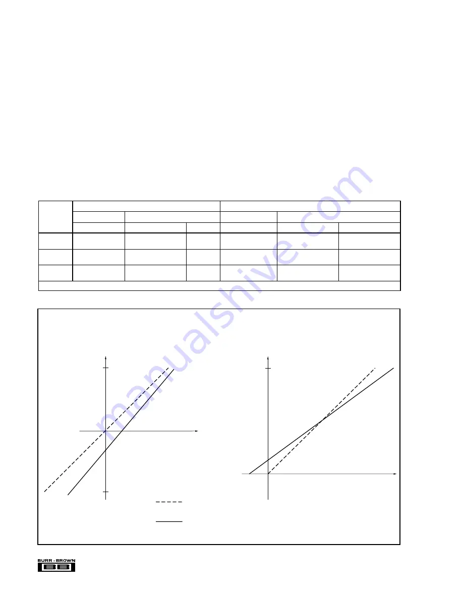
with and without the external resistors. Refer to Figure 8 for
typical shifts in the transfer functions which occur when the
external resistors are removed.

To further analyze the effects of removing any combination
of the external resistors, consider Figure 9. The combination
of the external and the internal resistors form a voltage
divider which reduces the input signal to a 0.3125V to
2.8125V input range at the CDAC. The internal resistors are
laser trimmed to high relative accuracy to meet full specifi-
cations. The actual input impedance of the internal resistor
network looking into pin 1 or pin 3 however, is only accurate
to 

±

20% due to process variations. This should be taken into

account when determining the effects of removing the exter-
nal resistors.

REFERENCE

The ADS7806 can operate with its internal 2.5V reference or
an external reference. By applying an external reference to

INPUT

RANGE

W/ RESISTORS

W/OUT RESISTORS

W/ RESISTORS

W/OUT RESISTORS

(V)

RANGE (mV)

RANGE (mV)

TYP (mV)

RANGE (% FS)

RANGE (% FS)

TYP

±

10

–10 

 BPZ 

 10

 BPZ 

 35

+15

–0.4 

 G 

 0.4

–0.3 

 G 

 0.5

+0.05

0.15 

 G

(1)


 0.15

–0.1 

 G

(1)


 0.2

+0.05

0 to 5

–3 

 UPO 

 3

–12 

 UPO 

 –3

–7.5

–0.4 

 G 

 0.4

–1.0 

 G 

 0.1

–0.2

0.15 

 G

(1)


 0.15

–0.55 

 G

(1)


 –0.05

–0.2

0 to 4

–3 

 UPO 

 3

–10.5 

 UPO 

 –1.5

–6

–0.4 

 G 

 0.4

–1.0 

 G 

 0.1

–0.2

–0.15 

 G

(1)


 0.15

–0.55 

 G

(1)


 –0.05

–0.2

Note: (1) High Grade.

OFFSET ERROR

GAIN ERROR

TABLE VIII.  Range of Offset and Gain Errors with and without External Resistors

Digital Output

(b) Unipolar

–Full Scale

+Full Scale

Analog Input

Digital Output

(a) Bipolar

–Full Scale

+Full Scale

Analog Input

Typical Transfer Functions
With External Resistors

Typical Transfer Functions
Without External Resistors

FIGURE 8. Typical Transfer Functions With and Without External Resistors.

Summary of Contents for PCM-A/D-12

Page 1: ...OPERATIONS MANUAL PCM A D 16 PCM A D 12 WinSystems reserves the right to make changes in the circuitry and specifications at any time without notice Copyright 1996 by WinSystems All Rights Reserved...

Page 2: ...REVISION HISTORY P N 403 0230 000 ECO Number Date Code Rev Level Originated 960206 B 97 31 970513 B1 WinSystems The Embedded Systems Authority...

Page 3: ...Selection 2 3 2 6 Input Connector Pin Definitions 2 8 2 7 PC 104 Bus Pin Definitions 2 8 2 8 Connector Jumper Summary 2 9 3 PCM A D Programming Reference 3 1 I O Register Definitions 3 1 3 2 Conversi...

Page 4: ...6 and PCM A D 12 are low cost general purpose successive approxi mation analog to digital converters The PCM A D 16 uses the Burr Brown ADS7807 16 bit converter while the PCM A D 12 uses the Burr Brow...

Page 5: ...5mA typ w o DC DC converter installed 1 3 2 Mechanical Dimensions 3 6 X 3 8 X 0 6 PC Board FR4 Epoxy glass with 2 signal layers and 2 power planes with screened component legend and plated through ho...

Page 6: ...l Time Technical Support may also be requested by FAX at 817 548 1358 The PCM A D has 16 single ended inputs or 8 differential inputs and converts in 25 30uS The end of conversion can be determined in...

Page 7: ...The end of conversion interrupt may be routed to any unused PC 104 interrupt line us ing the jumper block at J9 The illustration below shows the relationship between the jumper position and the interr...

Page 8: ...lled or damage to the PCM A D board other PC 104 modules the CPU board or the power supply may result Boards provided with DC DC converters from the factory will not have the jumper posts installed at...

Page 9: ...to the following table Full Scale Range 0 0 5 0 Volts Least Significant Bit LSB 76uV 16 Bit or 1 22mV 12 Bit Full Scale FS 1LSB 4 999924V 16 Bit or 4 99878V 12 Bit FFFFH Midscale 2 50V 8000H One LSB...

Page 10: ...table Full Scale Range 10 0V Least Significant bit 305uV 16 Bit or 4 88mV 12 Bit Full Scale FS 1LSB 9 999695V 16 Bit or 9 99512 12 Bit 7FFFH Midscale 0 0V 0000H One LSB below Midscale 305uV 16Bit or...

Page 11: ...5 0 Volts Least Significant Bit LSB 76uV 16 Bit or 1 22mV 12 Bit Full Scale FS 1LSB 4 999924V 16 Bit or 4 99878V 12 Bit FFFFH Midscale 2 50V 8000H One LSB Below Midscale 2 4999924V 16 Bit or 2 49878...

Page 12: ...g this mode Two s complement binary values are read from the converter per the following table Full Scale Range 10 0V Least Significant bit 305uV 16 Bit or 4 88mV 12 Bit Full Scale FS 1LSB 9 999695V 1...

Page 13: ...nded Input Channels Differential Input Channels B1 o o A1 B2 o o A2 B3 o o A3 B4 o o A4 B5 o o A5 B6 o o A6 B7 o o A7 B8 o o A8 B9 o o A9 B10 o o A10 B11 o o A11 B12 o o A12 B13 o o A13 B14 o o A14 B1...

Page 14: ...nector 2 8 J4 Input range select jumper 2 3 J5 Mode select differential vs single ended 2 3 J6 DC DC Converter Enable 2 3 J7 Mode Select binary vs two s complement 2 3 J8 I O Address Select 2 2 J9 Int...

Page 15: ...t Only MSB Data BASE 3 Reserved Reserved Each Register will be examined in more detail 3 1 1 Base Address Write Register Channel Select D7 N A D6 N A D5 N A D4 N A D3 Bit 3 of select nibble D2 Bit 2 o...

Page 16: ...0 of select nibble Writing a value to the BASE 1 I O address not only selects the channel number as en coded in bits 3 0 but after a hardware settling delay of approximately 6uS starts a conver sion T...

Page 17: ...he Channel Select Start Conver sion register This method of starting the converter allows for maximum throughput when repetitively converting on the same channel as no multiplexer settling time is req...

Page 18: ...BASE_ADDRESS 0x110 unsigned convert int channel_number unsigned return_value Start the conversion by writing to the Select Start conversion Register outportb BASE_ADDRESS 1 channel_number Now wait for...

Page 19: ...5 WinSystems The Embedded Systems Authority Channel RAW HIGH LOW DATA CURRENT MAX MIN VOLTAGE Number DATA DATA DATA DEV VOLTAGE VOLTAGE VOLTAGE DEVIATION 00 FFFF FFFF FFFF 0000 5 0000 5 0000 5 0000 0...

Page 20: ...it and 16 bit M Toggle the conversion mode This key toggles the conversion mode between Interrupt Mode and Polled Mode When in the Interrupt Mode a counter in the lower right corner will display the n...

Page 21: ...ey 7 Adjust R4 counter clockwise for a reading corresponding to the input source Some lower bit deviation may be experienced and is normal 8 Set the input source to 5 00 volts Hit R to clear the curre...

Page 22: ...4 APPENDIX A PCM A D Parts Placement Guide...

Page 23: ...5 APPENDIX B PCM A D Parts List...

Page 24: ...45 002 IC 74HCT245DW SM U7 I 1 0 2 611 0221 002 IC 74HC221D SO 16 U8 I 1 0 2 612 0688 002 IC 74HCT688AF SM U9 I 1 0 2 200 0064 100 SCKT 64 POS STK QPHF2 64 020 1Z PLAST J10 CLIP PIN B10 MUST BE HAND S...

Page 25: ...UT HEX NYLON 4 40 I 2 0 2 525 0304 001 SIZE 3 COIN ENVLPE 2 5 X 4 25 50260 SIZE 3 COIN ENVELOPE 2 1 2 X 4 1 4 I 1 0 SUB ASSEMBLY TOTAL KIT PCM STANDOFF 2 ARLIN 6 Items TOP ASSEMBLY TOTAL PCM A D12 16...

Page 26: ...6 APPENDIX C BURR BROWN ADS7806 ADS7807 Datasheet Reprint...

Page 27: ...re range CDAC 6k 40k 10k BUSY Parallel and Serial Data Out Comparator Buffer 20k R1IN R2IN REF Successive Approximation Register and Control Logic Clock Power Down BYTE CS R C 40k Internal 2 5V Ref Re...

Page 28: ...LSB Gain Error 0 2 0 1 Full Scale Error 3 4 0 5 0 25 Full Scale Error Drift 7 5 ppm C Full Scale Error 3 4 Ext 2 5000V Ref 0 5 0 25 Full Scale Error Drift Ext 2 5000V Ref 0 5 ppm C Bipolar Zero Error...

Page 29: ...og input is acquired to rated accuracy A Convert Command after this delay will yield accurate results 6 All specifications in dB are referred to a full scale input 7 Usable Bandwidth defined as Full S...

Page 30: ...ata bit 7 if BYTE is LOW Hi Z when CS is HIGH and or R C is LOW 14 DGND Digital Ground 15 D2 O LOW if BYTE is HIGH Data bit 6 if BYTE is LOW Hi Z when CS is HIGH and or R C is LOW 16 D1 O LOW if BYTE...

Page 31: ...OISE DISTORTION vs TEMPERATURE fIN 1kHz 0dB fS 10kHz to 40kHz 74 0 73 9 73 8 73 7 73 6 75 50 25 0 25 50 75 100 125 150 Temperature C SINAD dB A C PARAMETERS vs TEMPERATURE fIN 1kHz 0dB 110 105 100 95...

Page 32: ...Percent From Ideal mV From Ideal ENDPOINT ERRORS UNIPOLAR RANGES Temperature C 75 50 25 0 25 50 75 100 125 150 Percent From Ideal All Codes INL UPO Error FS Error 4V Range FS Error 5V Range FS Error...

Page 33: ...will be valid on both the rising and falling edges of the data clock BUSY going HIGH can be used to latch the data All convert commands will be ignored while BUSY is LOW The ADS7806 will begin tracki...

Page 34: ...lel data in Straight Binary or Binary Two s Complement data output format If SB BTC pin 7 is HIGH the output will be in SB format and if LOW the output will be in BTC format Refer to Table V for ideal...

Page 35: ...tput tie EXT INT pin 8 HIGH and DATACLK pin 18 LOW SDATA pin 19 should be left unconnected The parallel output will be active when R C pin 22 is HIGH and CS pin 23 is LOW Any other combination of CS a...

Page 36: ...ted or during conversion n 1 An obvious way to simplify control of the converter is to tie CS LOW and use R C to initiate conversions While this is perfectly acceptable there is a possible problem whe...

Page 37: ...xternal Clock EXT INT Tied HIGH Read after Conversion EXTERNAL DATACLK CS 0 Bit 11 MSB R C BUSY SDATA TAG 1 2 3 11 12 13 14 Bit 10 Bit 1 Bit 0 LSB Tag 0 Tag 1 Tag 1 Tag 2 Tag 11 Tag 12 Tag 13 Tag 14 T...

Page 38: ...onous data clock can cause digital feedthrough degrading the converter s perfor mance Refer to Table VI and Figure 6 TAG FEATURE TAG Pin 20 inputs serial data synchronized to the external or internal...

Page 39: ...l yield either positive full scale or negative full scale digital outputs respectively There will be no wrapping or folding over for analog inputs outside the nominal range CALIBRATION HARDWARE CALIBR...

Page 40: ...er which reduces the input signal to a 0 3125V to 2 8125V input range at the CDAC The internal resistors are laser trimmed to high relative accuracy to meet full specifi cations The actual input imped...

Page 41: ...an internal buffer for the reference voltage See Figure 10 for characteristic impedances at the input and output of the buffer with all combinations of power down and reference down REF REF pin 5 is a...

Page 42: ...ca tions the ADS7806 uses 90 of its power for the analog circuitry The ADS7806 should be considered as an analog component The 5V power for the A D should be separate from the 5V used for the system s...

Page 43: ...data input of the microcontroller is tied to the MSB D7 of the ADS7806 instead of the serial output SDATA Using D7 instead of the serial port offers tri state capability which allows other peripheral...

Page 44: ...and transmit sections of the interface are decoupled asynchronous mode and the transmit section is set to generate a word length frame sync every other transmit frame frame rate divider set to two The...

Page 45: ...25 s max while consuming only 35mW max Laser trimmed scaling resistors provide standard industrial input ranges of 10V and 0V to 5V In addition a 0V to 4V range allows develop ment of complete single...

Page 46: ...4V Ranges 3 mV Unipolar Zero Error Drift 0V to 5V 0V to 4V Ranges 0 5 ppm C Recovery Time to Rated Accuracy 2 2 F Capacitor to CAP 1 ms from Power Down 5 Power Supply Sensitivity 4 75V VS 5 25V 8 LSB...

Page 47: ...o rated accuracy A Convert Command after this delay will yield accurate results 6 All specifications in dB are referred to a full scale input 7 Usable Bandwidth defined as Full Scale input frequency a...

Page 48: ...sion With CS LOW a rising edge on R C enables the parallel output 23 CS I Internally OR d with R C If R C is LOW a falling edge on CS initiates a new conversion If EXT INT is LOW this same falling edg...

Page 49: ...0 1k 10k 100k 1M 100 80 90 70 60 50 40 30 20 10 SINAD dB TYPICAL PERFORMANCE CURVES At TA 25 C fS 40kHz VDIG VANA 5V using internal reference and fixed resistors shown in Figure 7b unless otherwise sp...

Page 50: ...25 C fS 40kHz VDIG VANA 5V using internal reference and fixed resistors shown in Figure 7b unless otherwise specified 3 2 1 0 1 2 3 16 Bit LSBs 0 65535 57344 49152 40960 32768 24576 16384 8192 Decimal...

Page 51: ...stay LOW until the conversion is completed and the output register is updated If BYTE pin 21 is LOW the 8 most significant bits will be valid when BUSY rises if BYTE is HIGH the 8 least significant b...

Page 52: ...f control pins CS can be tied LOW using R C to control the read and convert modes This will have no effect when using the internal data clock in the serial output mode However the parallel output and...

Page 53: ...el Outputs Hi Z State BUSY R C DATA BUS High Byte t3 t4 t21 t21 t1 t21 t21 BYTE t21 t21 t21 t21 t21 t21 Hi Z State Low Byte Hi Z State t9 t12 t9 t12 CS FIGURE 2 Conversion Timing with Parallel Output...

Page 54: ...So with CS LOW either R C and or DATACLK must be LOW during this period to avoid losing valid data SERIAL OUTPUT Data can be clocked out with the internal data clock or an external data clock When usi...

Page 55: ...External Clock EXT INT Tied HIGH Read after Conversion EXTERNAL DATACLK CS 0 Bit 15 MSB R C BUSY SDATA TAG 1 2 3 4 16 17 18 Bit 14 Bit 1 Bit 0 LSB Tag 0 Tag 1 Tag 1 Tag 2 Tag 15 Tag 16 Tag 17 Tag 18 T...

Page 56: ...onous data clock can cause digital feedthrough degrading the converter s perfor mance Refer to Table VI and Figure 6 TAG FEATURE TAG Pin 20 inputs serial data synchronized to the external or internal...

Page 57: ...s for Hardware Calibration see Figure 7a 200 1 2 3 4 5 6 AGND2 REF CAP R2IN AGND1 R1IN 2 2 F 2 2 F 33 2k 100 VIN 200 1 2 3 4 5 6 AGND2 REF CAP R2IN AGND1 R1IN 2 2 F 2 2 F 100 5V 66 5k VIN 200 1 2 3 4...

Page 58: ...transfer functions which occur when the external resistors are removed To further analyze the effects of removing any combination of the external resistors consider Figure 9 The combination of the ex...

Page 59: ...the SNR and SINAD The REF pin should not be used to drive external AC or DC loads See Figure 10 The range for the external reference is 2 3V to 2 7V and determines the actual LSB size Increasing the r...

Page 60: ...upply All the ground pins of the A D should be tied to an analog ground plane separated from the system s digital logic ground to achieve optimum performance Both analog and digital ground planes shou...

Page 61: ...6 will yield the 3 distribution or 99 7 of all codes Statistically up to 3 codes could fall outside the 5 code distribution when executing 1000 conversions The ADS7807 has a TN of 0 8 LSBs which yiel...

Page 62: ...ansfer In addition CPOL and CPHA should be set to zero SCK normally LOW and data captured on the rising edge The command control byte for the eight bit transfer should be set to 20H and for the sixtee...

Page 63: ...d length 16 bits Convert Pulse width as close to the minimum value specified in this data sheet will offer the best performance See the Starting A Conversion section of this data sheet for details on...

Page 64: ...7 APPENDIX D PCM A D Demo Software Source Listing...

Page 65: ...ample source code on an as is basis and makes no warranty as to fitness of purpose In no event shall WinSystems be liable for consequential incidental or special damages of any kind through the use of...

Page 66: ...pt_count 0 int mode 0 Program entry point void main unsigned char lsb msb char c unsigned low high current int channel channel_number 0 To start we will install our interrupt handler saving the old ha...

Page 67: ...y mode dependent screen information gotoxy 1 25 switch mode case 0 printf Scale 0 to 5 Volts Single Ended break case 1 printf Scale 10 to 10 Volts Single Ended break case 2 printf Scale 0 to 5 Volts D...

Page 68: ...keys recognized are r reset deviation values t toggle voltage mode m toggle betweent interrupt and polled mode c getch if c r for channel 0 channel max_channel channel flag channel 0 else if c t mode...

Page 69: ...t s value if interrupt_mode outportb AD_BASE 1 channel Start the conversion wait_complete wait for the channel to complete lsb inportb AD_BASE 1 assemble the word result msb inportb AD_BASE 2 from the...

Page 70: ...t_val printf 8 4f float low_val channel 0x8000 float full_count full_scale offset_val printf 8 4f float high_val channel 0x8000 low_val channel 0x8000 float full_count full_scale else printf 8 4f floa...

Page 71: ...the arrays for display by the foreground routine void interrupt ad_isr int temp unsigned char lsb msb unsigned current interrupt_count temp channel_number lsb inportb AD_BASE 1 msb inportb AD_BASE 2 c...

Page 72: ...val temp 0x8000 high_val temp current else if current low_val temp low_val temp current if current high_val temp high_val temp current Send the EOI to the interrupt controller to re arm for next inter...

Page 73: ...8 APPENDIX E PCM A D Schematic Diagrams...

Page 74: ...2 5V DRQ2 12V OWS 12V GND SMEMW SMEMR IOW IOR DACK3 DRQ3 DACK1 DRQ1 DACK0 CLK IRQ7 IRQ6 IRQ5 IRQ4 IRQ3 DACK2 T C BALE 5V OSC GND GND U6 22V10 1 2 3 4 5 6 7 8 9 10 11 13 14 15 16 17 18 19 20 21 22 23 C...

Page 75: ...IN5 IN6 IN7 IN8 A0 A1 A2 EN GND V V OUT R1 RESERVED U3 508A 4 5 6 7 12 11 10 9 1 16 15 2 14 3 13 8 IN1 IN2 IN3 IN4 IN5 IN6 IN7 IN8 A0 A1 A2 EN GND V V OUT J7 1 2 C14 1 1 2 R2 RESERVED C15 1 1 2 U2 INA...

Page 76: ...WARRANTIES BY WINSYSTEMS EXCEPT AS STATED HEREIN THERE ARE NO OTHER WARRANTIES EXPRESS OR IMPLIED INCLUDING BUT NOT LIMITED TO THE IMPLIED WARRANTIES OF MERCHANTABILITY AND FITNESS FOR A PARTICULAR P...

Reviews: