


ENGLISH
16
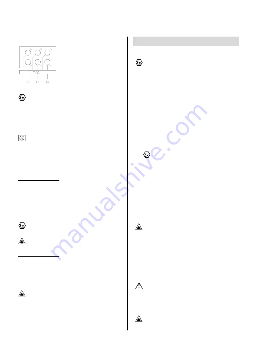
7.3.4
Y /
STARTER :
Grounding of the complete pumpset will be performed with
special care. Earthing will avoid any electrostatic accumulation in
components of the pumpset. Each part of the pumpset should be
connected to earth with a correctly calibrated bonding strap or cable
(motor winding, motor frame, coupling guard, pump baseframe).
7.4
USE OF A FREQUENCY INVERTER
When pump is used with a variable speed drive, make sure that
the frequency inverter instructions and operating manual is available
and known.
The electric motor that is supplied with the pump may be connected
under conditions to a VSD. Variable speed will be used to reach pump
required duty point on site. To ensure a reliable use of the equipment a
few precautions should be taken :
ELECTRICAL REQUIREMENTS :
-
Variable frequency drive will not generate voltage peak higher than
850V (motor phases isolation) and dU/dt values higher than 2500
V/µs (winding isolation). If those values can be reached, a filter
should be installed : ask inverter manufacturer for proper selection
and motor manufacturer for limit values.
-
Choose a vector control inverter or use a quadratic V/F control
inverter.
-
Check that motor nominal voltage is never exceeded.
Power supply cable should comply to ATEX regulation. Ensure that
motor winding is equipped with CTP temperature sensors inside.
A physical barrier should separate power supply cables and low
voltage cables to avoid analog signal distortion.
HYDRAULIC REQUIREMENTS :
-
For all possible speeds, check that the pump NPSH
R
is always lower
than system NPSH
A
.
MECHANICAL REQUIREMENTS :
-
Lower speed should not fall under 40% of pump nominal speed to
avoid any vibrations and an unstable flow.
The harmonic currents that are created by the VSD pass through
motor ball bearings. Standard ball bearings can be used up to 55KW. For
higher installed power (see engraved power on motor name plate), the
motor should be equipped with isolated ball bearings (specific ball
bearing) or with isolated bearing housing (and standard ball bearing).
8
START-UP
8.1
PRE-COMMISSIONING
If the pump is installed in a potentially explosive atmosphere or
when dangerous or polluting fluids are pumped, it is advised (Zone 2) or
requested (zone 1) to install additional protection devices.
Check following points :
-
Pump flow is always higher than authorized continuous minimum
flow,
-
Pump never runs dry,
-
Surface temperature bearings housings is lower than the maximum
admissible surface temperature in selected ATEX zone,
-
Pressure on discharge side of the pump is lower than pump
maximum allowable working pressure.
-
Set alarm and stop trips of sensors.
IN EVERY CASES CHECK :
-
Quality of electrical connections,
-
Protection devices are installed,
-
Auxiliary lubrication piping is connected and running,
-
Flanges connections,
-
Minimum liquid level,
-
Motor direction of rotation is correct,
-
Oil level was checked and greasing of ball bearings has been done,
-
Coupling guard is installed.
8.2
FILLING / VENTING
The volute casing is always submerged. Manual filling is not necessary.
Due to its design, the pump does not need to be vented.
8.3
START-UP
If a barrier fluid, flushing fluid, cooling fluid or a heating fluid is
used, check that auxiliary systems are activated and working correctly
before pump start-up.
Close isolating valve on pump discharge side.
Open all valves in suction line.
Proceed to pump priming (if not already done). Pump casing and
suction pipe should be completely filled with fluid.
Turn the pump on and check discharge pressure increase. Compare
this pressure to the shutoff pressure available on the hydraulic curve
In order to avoid an important overheating of the liquid inside the
pump the pump should not work more than 20 to 30 seconds against a
closed discharge valve.
If expected pressure is reached then progressively open the discharge
valve.
If there is no liquid delivered or if discharge pressure is too low
then see chapter “trouble shooting”.
Summary of Contents for Norma V Series
Page 2: ......
Page 34: ...FRAN AIS 34 13 DECLARATION CE...
Page 35: ...FRAN AIS 35...
Page 36: ...FRAN AIS 36...
Page 68: ...ENGLISH 34 13 EC DECLARATION OF CONFORMITY...
Page 69: ...ENGLISH 35...
Page 70: ...ENGLISH 36...
Page 73: ...5 1 1 1 2 2 1 2 2 WILO 2 3 2 4 2 4 1 25 68 5 C...
Page 74: ...6 2 4 2 2 4 3 2 5 WILO 2 6 2 7...
Page 77: ...9 3 3 1 3 2 3 3 6 WILO 3 4 25 3 4 1...
Page 83: ...15 7 7 1 ATEX 1 5 7 1 1 7 1 2 1 2 3 7 1 3 7 1 4 7 2 7 2 1 7 2 2...
Page 84: ...16 7 2 3 7 2 4 7 3 230 400 400 400 690 690 60079 14 7 3 1 Y 230 400 400 690 7 3 2 U...
Page 85: ...17 7 3 3 U 3 7 3 4 7 4 850 dU dt 2500 ATEX NPSHR NPSHA 40 55 8 8 1 2 1 ATEX...
Page 86: ...18 8 2 8 3 20 30 8 4 mwc HMTmwc Pbar x 100 d x 9 806 d CS ATEX 1 8 5 WILO 9 9 1...
Page 89: ...21 V18 TM TM 2 90 9 3 2 9 3 2 1 9 3 2 2 9 3 2 3 9 3 2 4 TM TH 9 3 2 5 6581 9200 4590A...
Page 98: ...30 2100 7416 M8 5 5 M6 4 7416 3 2 7412 9 3 9 3320 3250...
Page 101: ...33 10 SRV NPSH NPSH NPSH NPSH NPSH...
Page 102: ...34 11 12 12 1 12 2 90 12 3 2 DIN 24296 1 1 1 1 2 1 1 4 1 2 2...
Page 103: ...35 13...
Page 104: ...36...
Page 105: ...37...
Page 106: ...38...
Page 107: ...39...
Page 108: ...40...
Page 111: ......


