


en
Installation and operating instructions • Drive for Wilo-Helix2.0-VE / Wilo-Medana CH3-LE • Ed.01/2022-06
25
7.2
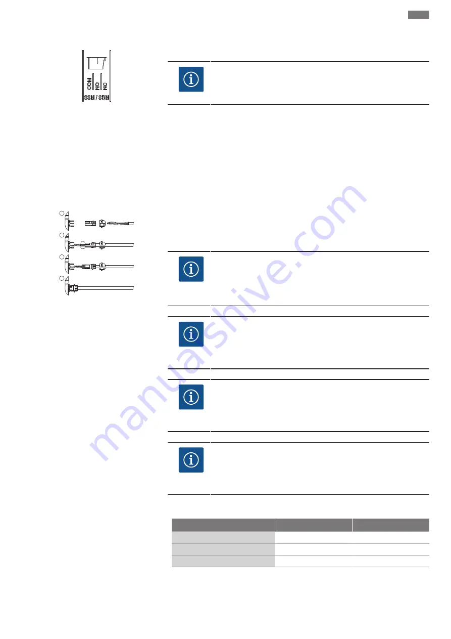
Connection of SSM / SBM
18 19 20
Fig. 14: Terminals for SSM / SBM
SSM (collective fault signal) and SBM (collective run signal) are connected to terminal 18 The
cables of the electrical connection for SBM / SSM do not have to be shielded.
NOTICE
A maximum of 230 V may be applied between the contacts of the relays of
SSM / SBM, never 400 V!
SSM / SBM are designed as changeover contacts and can each be used as a normally open
contact or normally closed contact. When the drive is voltage-free, the contact is normally
closed contact. The following applies in SSM configuration:
•
If a fault is present, the contact at NC is normally open contact.
•
The converter bridge to NO is closed.
The following applies in SBM configuration:
•
Depending on the configuration, the contact is set to NO or NC.
7.3
Connection of digital, analogue
and bus inputs
1
2
3
4
Fig. 15: Shield clamp
The cables of the digital inputs, analogue inputs and bus communication must be shielded
via the metal threaded cable gland of the cable bushing 4, 5 and 6 (Fig. 8). When used for ex-
tra-low voltage cables, up to three cables can be passed through for each threaded cable
gland. Use the appropriate multiple sealing inserts for this purpose.
NOTICE
If two cables have to be connected to one 24 V supply terminal, provide a
solution on-site!
Only one cable per terminal may be connected to the pump!
NOTICE
The terminals of the analogue inputs, digital inputs and Wilo Net meet the
"safe isolation" requirement (according to EN61800-5-1) to the mains
terminals, the terminals SBM / SSM (and vice versa).
NOTICE
The control is designed as a SELV (Safe Extra Low Voltage) circuit. In this
way, the (internal) supply fulfils the requirements for safe separation of
the supply. GND is not connected to PE.
NOTICE
The drive can be switched on and off without intervention from the oper-
ator. This can be done, for example, using the control function, by external
BMS connection or also by the function Ext. Off.
7.4
Pressure sensor connection
If pressure sensor is connected carry out the cable assignment as follows:
Cable wire
Terminal
Function
1
+24 V
+24 V
2
In1
Signal
3
GND
Ground
Table 6: Connection; pressure sensor cable


