T
ake note of the corresponding installation regulations for
E
x
applications
.
I
n particular
,
make sure that no potential equalisation
currents
fl
ow over the cable screen
.
I
n case of grounding on both sides
this can be achieved by the use of a capacitor or a separate potential
equalisation
.
5
.
2
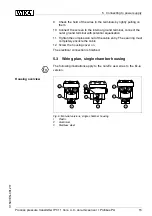
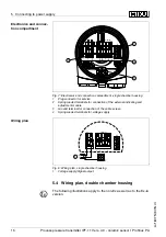
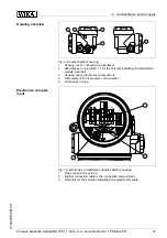
C
onnection procedure
P
roceed as follows
:
1
U
nscrew the housing cover
2
I
f an indicating and adjustment module is installed
,
remove it by
turning it slightly to the left
.
3
L
oosen compression nut of the cable entry
4
R
emove approx
.
10
cm
(
4
in
)
of the cable mantle
,
strip approx
.
1
cm
(
0
.
4
in
)
insulation from the ends of the individual wires
5
I
nsert the cable through the cable gland into the sensor
6
L
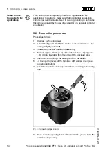
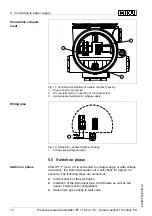
ift the opening levers of the terminals with a screwdriver
(
see
following illustration
)
7
I
nsert the wire ends into the open terminals according to the wiring
plan
F
ig
.
5
:
C
onnection steps
6
and
7
8
P
ress down the opening levers of the terminals
,
you will hear the
terminal spring closing
S
elect connec
-
tion cable for
E
x
applications
14
P
rocess pressure transmitter
IPT
-
11
V
ers
.
4
.
0
-
ceramic sensor
•
P
ro
fi
bus
PA
5
C
onnecting to power supply
31547
-
EN
-
081211


