page 2 – 6
L-8 / Sep 2013
S U R F A C E C O N F I G U R A T I O N
L-8 / Jan 2015
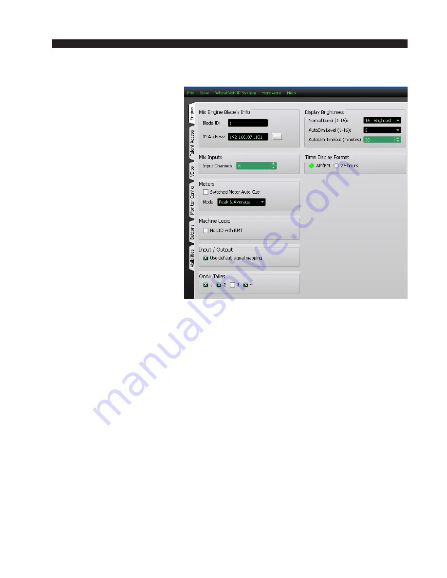
Engine Tab
Mix Engine Blade’s Info
– In
this section you will set the
Mix Engine
Blade ID
and the
IP Address
of the Engine to which
the surface will connect.
Once the control surface
has been associated with a
Mix Engine, the BLADE 3
will query the surface for its
configuration information and
then automatically generate the
required source and destination
signals. See Appendix 2 for
details.
Mix Inputs
– Not Used.
Meters
– The switched meter
on the surface’s meterbridge
displays the signal level of a user
selected source or the Cue signal
level when an input fader’s CUE
switch is activated. To activate
the Auto Cue function check the
Switched Meter Auto Cue
box.
Use the
Mode
dropdown box to choose from
Peak & Average
,
Peak Only
, or
Average Only
.
Machine Logic
– The purpose of this option is to allow the privileged operator to de-
termine the conditions under which START and STOP signals are sent in response to a
command to turn a channel ON or OFF. Channel ON and OFF commands can come from
two different sources:
• Surface – A channel can be turned ON or OFF by a surface action, such as pressing
the ON or OFF switch, or moving a fader if EFS has been enabled
• Remote (RMT) – A channel can be turned ON or OFF by sending it a command
from a system Logic I/O card via the RemOn and RemOff functions.
When the
No LIO with RMT
check box is checked, LIO signals are globally blocked
for all input faders if the channel ON and OFF commands are initiated from the system
Logic I/O card.
Input/Output
– In most cases, you will want the
Use default signal mapping
check box
to be checked, to insure that signals are properly mapped. This insures that the surface
signals appear at the designated connectors on the Console BLADE3. If you want to
re-arrange or re-purpose the signals, leave this check box unchecked.
OnAir Tallies
– There is an ON AIR indicator at the upper left corner of the surface
meterbridge. These check boxes will determine what Studio Tally VDip settings (see VDips
tab) will light the indicator when a channel is on. For example, if you only have an X in
OnAir Tallies 2, then the On AIR indicator will light only if a fader having a signal using
Studio Tallies 2 on the VDips tab is turned on. If 1 and 2 are both checked here then a
signal that uses Studio Tallies 1 or 2 on a fader that is ON will cause the ON AIR to light.
L-8 / Dec 2016


