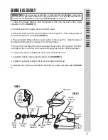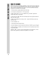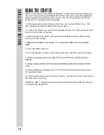
USING THE GRINDER
9
ENGLISH INSTRUCTIONS
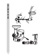
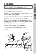
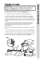
STUFFER ASSEMBLY
1. Place the Plastic Washer then the Bushing Set onto the end of the Auger
opposite the Pin
(FIGURE 3).
2. Carefully insert the Auger into the Grinder Head.
3. Place the Knife onto the square portion of the Auger Pin. The cutting edges of
the Knife should face outward
(FIGURE 4).
4. Place the Course Grinder Plate onto the round portion of the Auger Pin. Align
the tabs on the Grinder Plate with the notches in the Grinder Head.
5. Insert the Stuffing Funnel through the Front Ring Nut
(FIGURE 3).
6. Screw the Front Ring Nut/Stuffing Funnel assembly onto the Grinder Head
until firmly tight. DO NOT over-tighten the Front Ring Nut to avoid damaging the
Grinder during operation.
7. Loosen the Head Locking Knob on the side of the Motor Unit.
8. Install the Grinder Head onto the Motor Unit
(FIGURE 3).
9. Tighten the Head Locking Knob to secure the Grinder Head.
10. Install the Tray onto the Grinder Head. Press the Tray down until fully seated
(
FIGURE 3).
FIGURE 3
Front
Ring
Nut
Auger
Plastic
Washer
Grinder
Head
Motor
Unit
Tray
Stomper
Head
Locking
Knob
Knife
with
cutting
edges
facing
outward.
FIGURE 4
Grinding
Plate
Stuffing
Funnel
Reverse
Button
Power
Switch
Auger
Pin
Bush-
ing Set
WARNING!
Before cleaning, assembling or disassembling the
Grinder
, make sure
it is turned “off” and disconnected from the power source. Test to make sure there is
no power to the
Grinder
by switching the
Motor Unit
“on” and “off.”
Summary of Contents for 82-0102-W
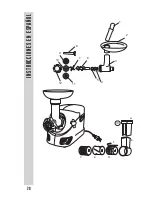
Page 4: ...1 3 4 6 7 8 9 10 11 12 5 2 ENGLISH INSTRUCTIONS 4 13 a b c e d f...
Page 15: ......
Page 19: ......
Page 20: ...1 3 4 6 7 8 9 10 11 12 5 2 13 a b c e d f 20 INSTRUCCIONES EN ESPA OL...
Page 31: ......
Page 35: ......
Page 36: ...1 3 4 6 7 8 9 10 11 12 5 2 13 a b c e d f INSTRUCTIONS EN FRAN AIS 36...
Page 47: ......


