Pro-EC44 2-Loop Graphical Profile Controller & Recorder
Pro-EC44 Product Manual - 59540-2 September 2014
Page 221
On-Off Differential
A switching differential, centred about the setpoint, when using On-o
ff control. Relay ‘chatter’
can be eliminated by proper adjustment of this parameter, but too large a value may increase
process variable oscillation to unacceptable levels. On-off differential is also known as
hysteresis or deadband.
Also refer to: Input Span; On-Off Control; PID Sets; Process Variable; Relay and Setpoint
On-Off Hysteresis
-
Operation Mode
The mode used during normal operation of the instrument. It can be accessed from the main
menu, and is the usual mode entered at power-up. The screens shown include a main
screen with bar-graphs, trend views, information about the process, alarms plus optionally,
selection of auto/manual control, control output disabling. Recorder and profiler information
can be displayed if these features are fitted. Up to 50 configuration menu screens also can
be shown in operation mode if set to do so with the PC software. In this mode screens are
not protected by a lock code.
Refer to the Operation Mode information in the Configuration & Use section.
Also refer to: Bar-Graphs; Configuration Mode; Custom Display Mode; Display Configuration;
Lock Codes; Main Menu; PC Software; Profiler Setup Menu; Recorder Menu and Trend
Display.
Output Configuration
A sub-menu of configuration mode used to adjust the parameters that relate to the outputs.
Available settings include linear output type & scaling, output usage and retransmit output
scaling etc.
Boolean logical OR / AND can be used to combine alarms and/or events to a single output.
Also refer to: Configuration Mode; Logical Output Combinations and Linear Output.
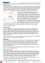
Overlap/Deadband
The Overlap/Deadband parameter defines the portion of the primary and secondary
proportional bands over which both outputs are active (called overlap), or neither is active
(called deadband). This is entered in display units, and is limited to -20% to +20% of the sum
of the two proportional bands. E.g. if the proportional bands were 2° and 8° (totalling = 10°)
the maximum overlap or deadband would be ±2°. Positive values = Overlap, negative values
= Deadband. The 5 PID sets for each control loop have their own overlap/deadband setting.
Overlap/deadband is not applicable if the primary output is set for on-off control or there is no
secondary output. If the secondary output is set for on-off, this parameter has the effect of
moving the on-off differential band of the secondary output to create the overlap or
deadband. When overlap/deadband = OFF, the edge of the secondary output differential
band coincides with the point at which the primary output is at 0% (off).
The effect of the Overlap/Deadband parameter is shown in the following table
Also refer to: On-Off Differential; On-Off Control; PID Sets; Primary Proportional Band and
Secondary Proportional Band.
Summary of Contents for Pro-EC44
Page 1: ...Pro EC44 2 Loop Graphical Profile Controller Recorder Pro EC44 User Guide 59540 2 ...
Page 2: ......
Page 6: ......

