English
TROUBLESHOOTING AND MAINTENANCE
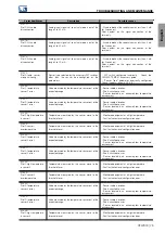
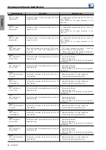
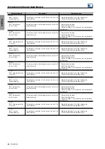
6.4 SOLUTIONS FOR THE MOST FREQUENT PROBLEMS
Table 6.2:
Solutions for the most frequent problems
Problem
Point to be verified
Corrective Action
Motor does not start
Incorrect
wiring
connection
1. Check all power and control connections. For instance, the digital inputs set
to Start/Stop, General Enable, or no external error shall be activated
Analog reference (if used)
1. Check if the external signal is properly connected
2. Check the status of the control potentiometer (if used)
Incorrect settings
1. Check if parameters are properly set for the application
Fault
1. Check if the inverter is not blocked due to a fault condition
2. Check if there is a short circuit between the terminals of the 24 Vdc power
supply
Motor stall
1. Decrease motor overload
Increase C3.2.1.1 (V/F) or
C3.3.5.1.2, C3.3.5.1.3, C3.3.5.1.4 and C3.3.5.1.5 (vector control)
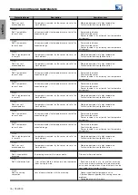
Motor speed fluctuates
(oscillates)
Loose connection
1. Stop the inverter, turn off the power supply, and check and tighten all power
connections
2. Check all internal connections of the inverter
Defective
reference
potentiometer
1. Replace potentiometer
Oscillation of the external
analog reference
1. Identify the cause of the oscillation. If it is caused by electrical noise, use
shielded cables or separate from the power and control wiring
Incorrect settings (vector
control)
1. Check parameters C2.2.2 and C2.2.4
2. Refer to the programming manual
Motor speed too high or
too low
Incorrect
settings
(reference limits)
1. Check if the content of C4.3.1.1.1 (minimum speed) and C4.3.1.1.2 (maximum
speed) are according to the motor and application
Control signal from the
analog reference (if used)
1. Check the level of the reference control signal
2. Check the programming gains and offset
Motor nameplate
1. Check if the motor has been properly sized for the application
Motor does not operate
in the field weakening
region (Vector Control)
Settings
1. Check C2.2.2 e C3.3.7.1
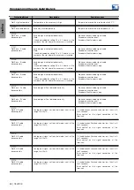
Off display
Keypad connections
1. Check the inverter keypad connection
Power supply voltage
1.
Rated
values
shall
be
within
the
limits
specified
below:
200-240 Vca power supply:
- Min: 187 Vca
- Max: 253 Vca
380-480 Vca power supply:
- Min: 323 Vca
- Max: 528 Vca
Blown fuses
1. Replace fuses
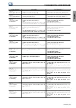
Low motor speed and
S1.1.4 =
C3.3.5.1.2
ou
C3.3.5.1.3
ou
C3.3.5.1.4
ou
C3.3.5.1.5
(motor
in
torque limitation),
for
C3.1.1 = 2 (vector with
encoder)
Encoder
signals
are
inverted
or
power
connection is inverted
1. Check if the signals
A
,
¯
A
,
B
,
¯
B
are correctly connected to the CFW900-
IOS
or to the accessory of inputs for incremental encoder (see the
CFW900-ENC-01 manual). If signals are properly installed, exchange two ofthe
output phases. For instance U and V.
6.5 INFORMATION FOR CONTACTING TECHNICAL SUPPORT
For technical support and servicing, it is important to have the following information in hand:
Inverter model.
Product serial number and manufacturing date contained in the identification label (see
Installed software version (see parameter S1.2.1).
Application data and inverter settings.
CFW900 | 89
Summary of Contents for CFW900
Page 2: ......

