English
INSTALLATION AND CONNECTION
Do not install heat sensitive components right above the inverter.
!
WARNING!
When one inverter is installed above another, use the minimum distance A + B, as shown in
, and divert the hot air blown by the lower inverter from the upper inverter.
Provide conduit for physical separation of the signal, control, and power conductors (refer to
b
3
c3
a3
e
3
d3
Øf3
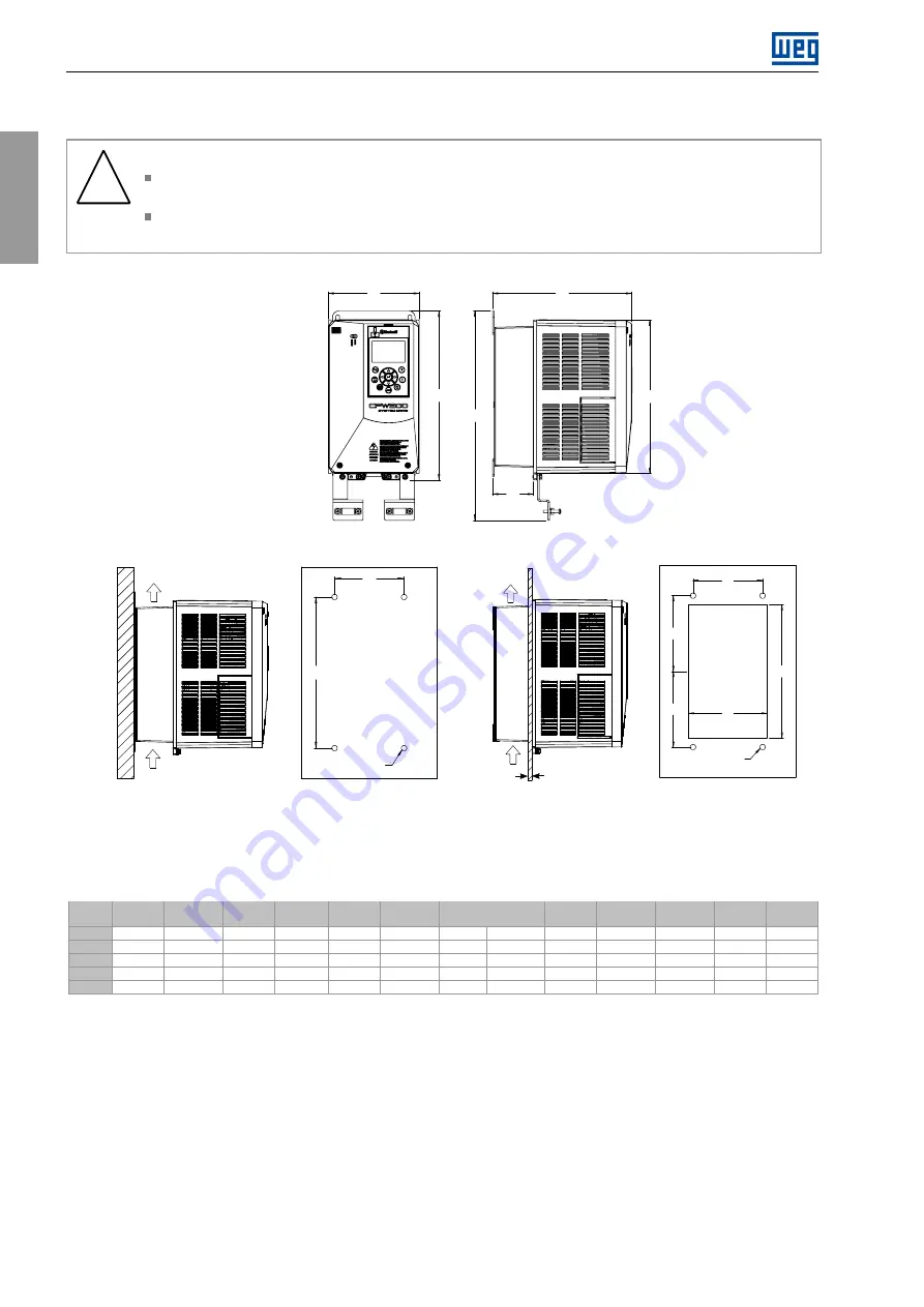
b) Surface mount.
c) Flange mount.
E
1
A1
F
1
C1
D1
B
1
a) External dimensions.
Máx. 3mm
Airflow
Øc2
a2
b
2
Airflow
Figure 3.1:
External dimensions of the inverters
Table 3.1:
External dimensions of the inverters
A1
B1
C1
D1
E1
F1
a2
b2
a3
b3
c3
d3
e3
Model
mm [in]
mm [in]
mm [in]
mm [in]
mm [in]
mm [in]
mm [in]
mm [in]
mm [in]
mm [in]
mm [in]
mm [in]
mm [in]
Frame A
145 [5.7]
245 [9.65]
222 [8.74]
65 [2.56]
269 [10.59]
333.5 [13.13]
115 [4.53]
250 [9.84]
124 [4.88]
120 [4.72]
120 [4.72]
138 [5.43]
228 [8.97]
Frame B
165.2 [6.5]
359.3 [14.15]
228 [8.98]
70.2 [2.76]
385 [15.16]
448.9 [17.67]
125 [4.92]
369.3 [14.54]
150 [5.9]
177.1 [6.97]
177.1 [6.97]
158 [6.22]
342 [13.46]
Frame C
200 [7.87]
430 [16.92]
294 [11.57]
136.4 [5.37]
460 [18.11]
519.3 [20.45]
150 [5.9]
425 [16.73]
175 [6.89]
210 [8.27]
210 [8.27]
188 [7.4]
405 [15.95]
Frame D
250 [9.84]
602 [23.7]
294 [11.57]
135 [5.31]
625 [24.6]
700 [27.56]
200 [7.87]
600 [23.6]
220 [8.66]
290 [11.41]
298 [11.73]
238 [9.37]
565 [22.24]
Frame E
335 [13.19]
620 [24.4]
358 [14.09]
169 [6.65]
675 [26.57]
763.4 [29]
200 [7.87]
650 [25.6]
275 [10.83]
318.5 [12.54]
318.5 [12.54]
316 [12.44]
620 [24.41]
*Tolerance of the dimensions d3 and e3: + 1.0 mm (+ 0.039 in)
*Tolerance of the other dimensions:
±
1.0 mm (
±
0.039 in)
12 | CFW900
Summary of Contents for CFW900
Page 2: ......


