English
INSTALLATION AND CONNECTION
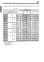
Table 3.11:
XC1 connector (CFW900-IOS)
Connector XC1
Pin
Name
Description
(1)
Default Function (if any)
1
AO1
Analog Output 1
Speed
2
AO2
Analog Output 2
Motor current
3,8,18,26
GND
Control circuit reference
4
C
RS-485 interface reference
5
A(-)
RS-485 interface negative
6
B(+)
RS-485 interface positive
7
VIN
+24 Vdc external power supply input
9,25
VOUT
+24 Vdc power supply output
10
DI1
Digital input 1
Run/Stop (Only in remote mode 2)
11
DI2
Digital input 2
12
DI3
Digital input 3
13
DI4
Digital input 4
14
DI5
Digital input 5
Input A for encoder
15
DI6
Digital input 6
Input B for encoder
16
COM
Common of the digital inputs
17
10V
10V power supply for potentiometer
19
AI1+
20
AI1-
Differential analog input 1
Speed reference (only in remote mode 2)
21
AI2+
22
AI2-
Differential analog input 2
23
DO1
Digital output 1
24
DO2
Digital output 2
(1)
For more information see the detailed specification in Table 8.11.
✓
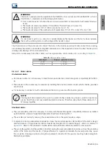
NOTE!
The digital outputs of the CFW900-IOS have freewheeling diodes for the 24 Vdc power supply of
the inverter control (inverter internal power supply or external power supply connected to VIN). If a
separate external 24 Vdc power supply is used to power the loads of the digital outputs, the state of
the outputs will remain indeterminate as long as the 24 V power supply of the inverter control is not
energized. If this characteristic is unwanted, the CFW900-REL-01 or CFW900-IOD-01 outputs must
be used.
Table 3.12:
Configuration of DIP switches for selecting the type of signal on the CFW900-IOS analog inputs/outputs
Input/Output
DIP switch
DIP position: Selected mode
(1)
Factory Default
AI1
S3:1
V: -10 a 10V; I: 4 a 20mA / 0 a 20 mA
V
AI2
S3:2
V: -10 a 10V; I: 4 a 20mA / 0 a 20 mA
V
AO1
S3:3
V: 0 a 10V; I: 4 a 20mA / 0 a 20 mA
V
AO2
S3:4
V: 0 a 10V; I: 4 a 20mA / 0 a 20 mA
V
(1)
The parameters referring to the inputs/outputs also need to be configured. Refer to the
programming manual.
40 | CFW900
Summary of Contents for CFW900
Page 2: ......

