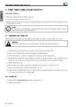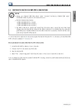
English
TROUBLESHOOTING AND MAINTENANCE
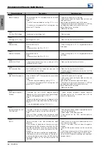
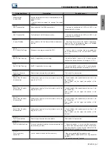
Protection/Alarm
Description
Possible causes
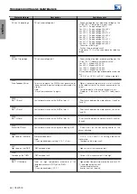
F021:
DC Link Undervoltage
DC link undervoltage fault.
- Supply voltage too low, producing voltage on the
DC link ( S2.7.1) below the minimum value:
Ud < 203 V - Supply voltage 200 V.
Ud < 210 V - Supply voltage 208-240 V.
Ud < 385 V - Supply voltage 380 V.
Ud < 405 V - Supply voltage 400-415 V.
Ud < 446 V - Supply voltage 440-460 V.
Ud < 487 V - Supply voltage 480 V.
Ud < 507 V - Supply voltage 500-525 V.
Ud < 557 V - Supply voltage 550-600 V.
Ud < 669 V - Supply voltage 660-690 V.
- Phase loss at the input.
- Fault on the pre-charge circuit.
- Parameter C1.1.2 with a value above the rated line
voltage.
F022:
DC Link Overvoltage
DC link overvoltage fault.
- Supply voltage too high, producing voltage on the
DC link ( S2.7.1) above the maximum value:
Ud > 400 V - Models 200-240 V.
Ud > 800 V - Models 380-480 V.
Ud > 1000 V - Models 500-600 V.
Ud > 1200 V - Models 660-690 V.
- Driven load inertia too high or deceleration ramp too
fast.
- C3.5.2.1 or C3.5.3.2 or C3.6.1 setting is too high.
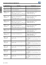
F025:
Pulse Feedback Error
Failure to compare the PWM pulses generated by
the control and the output voltages measured by the
inverter.
Note:
- Reset the inverter and try again.
- Motor is disconnected or motor is small in relation
to the rated current of the inverter connected to the
output.
- Possible defect on the inverter internal circuits.
- Problems in the circuit of the STO safety inputs
(XC2).
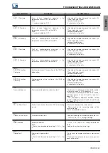
F030:
IGBT U Desat
Fault of desaturation on the IGBTs of arm U.
- Short circuit between the motor phases U and V or
U and W.
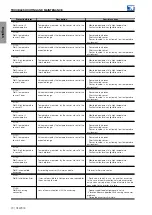
F034:
IGBT V Desat
Fault of desaturation on the IGBTs of arm V.
- Short circuit between the motor phases V and U or
V and W.
F038:
IGBT W Desat
Fault of desaturation on the IGBTs of arm W.
- Short circuit between the motor phases W and U or
W and V.
F042:
Brake IGBT Desat
Fault of desaturation on the dynamic braking IGBT.
- Short circuit on the connecting cables of the
dynamic braking.
A046:
High Load on the Motor
Motor overload alarm.
Note:
- It can be disabled by setting C7.4.1 = 0 or 2.
- C7.4.3, C7.4.4 and C7.4.5 setting is low for the
motor used.
- Overload on the motor shaft.
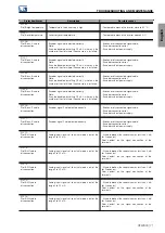
A047:
High Load on the IGBTs
IGBT overload alarm.
- High current at the inverter output:
F048:
Overload on the IGBTs
IGBT overload fault.
- Current at the inverter output is too high.
A050:
IGBT1 U Overtemp.
Alarm of high temperature measured in the
temperature sensors (NTC) of the IGBTs.
Note:
- It can be disabled by C7.5.1.
- High ambient temperature around the inverter (>50
◦
C) and high output current.
- Locked or defective fan.
- Inverter heat sink too dirty.
60 | CFW900
Summary of Contents for CFW900
Page 2: ......

